Introducing our newest Hanukkah menorah kit: Mega Menorah 9000!
This is a great new easy soldering kit to make a handsome and decently-sized menorah. Once built, it stands just over 6 inches (15 cm) tall, and is 7.5 inches (19 cm) wide.
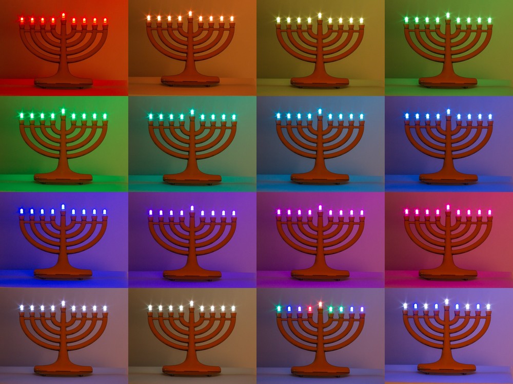
It’s USB powered, USB programmable with a built-in interface based on the Adafruit Trinket, and features 9 discrete RGB LED “pixels” that can produce all kinds of bright colors. Flickery flame effects built in too, of course.
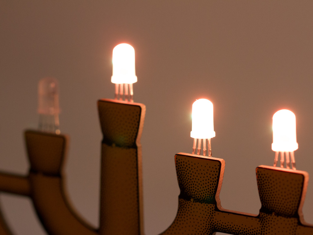
One of the cool things about this kit is that it has a unique “Trompe-l’œil” circuit board design that gives some illusion of a rounded 3D surface. As you can see above, it’s actually flat as a board.
To make it, we started with a 3D CAD model of what we wanted the circuit board to look like. The outer contours of the model became the outline of the circuit board. We then rendered the CAD model, and used our StippleGen 2 software to convert the resulting image into a vector stipple drawing— one that could eventually be converted into the artwork for the circuit board. All together it’s over 9000 stippled dots of black silkscreen! (To be more specific, there are roughly 17,000 dots on each side.)
MM9k FAQ: OK, but isn’t the name “Mega Menorah 9000” perhaps just slightly on the excessive side?
Yes, we must (grudgingly) admit that it is. It just slipped out when we were trying to come up with a working title for the project — a name that meant “better than deluxe” so as to distinguish this model from our old favorite Deluxe LED Menorah Kits.
Alas, it was funny. And so it stuck. And now, it’s too late.
There are two circuit boards in the kit. The “top” PCB is shaped like a menorah and the components (mainly just the nine WS2812-style LEDs) are for the most part hidden on the back side.
The base circuit board has rubber feet, the control buttons (color, night, reset), an ATtiny85 AVR microcontroller, USB power/programming jack, and a programming indicator LED. The circuit is actually an implementation of the Adafruit Trinket, which allows for reprogramming the microcontroller without requiring any hardware other than a regular USB cable.
MM9k FAQ: Why is there a binder clip there?
It’s an assembly jig that helps to align the parts in place so that it’s easy to build and looks neat. We’ll write more about it later.
And, wow does this thing do colors! The nine WS2812-style individually addressable RGB LEDs in 5 mm packages, look reminiscent of candle flames, but can be tuned to just about any color in the rainbow. From a control standpoint, it’s awfully nice that they’re managed by just a single pin of the microcontroller, and have the built-in ICs to handle colors and dimming.
Mega Menorah 9000 begins shipping this week.


Lovely product. It genuinely looks 3D in the pictures!
Am I right in thinking that this is not “open source” in the sense that nobody else can use the Adafruit VID and so nobody can legitimately make one? It’s not a question that would have occurred to me until recently, but the FTDI driver debacle has brought it rather into focus recently.
Ugi
The issue with the VID/PID is that you need to have your own values if you release your own derivative. There *are* ways to get your own for FOSS projects, for example the OpenMoko method: http://wiki.openmoko.org/wiki/USB_Product_IDs
That’s an interesting link, but if you used one of those PIDs you couldn’t just modify the product – you would need a new driver and a new version of AVRdude & probably many other things. I assume that’s one of the reasons you use Adafruit’s VID/PID – it’s already recognised as a TinyISP by AVRdude etc.
More than that, however, you couldn’t even make this exact product using the same design & code because that would be using Adafruit’s VID, which is not allowed. Of course there wouldn’t be much sense in doing that, since I can’t imagine you could make this as a one-off for $45, but as a hypothetical point an individual maker could not duplicate this device at home because of the VID rules as I (rather poorly I’ll admit) understand them.
Using USB directly just seems to open a can of worms I was not previously aware of.
Ugi
Nice writeup on Hackaday BTW
Brilliant! I love this AND the name. The color choice, the flicker, the trompe l’oeil, the control = awesome. And, it’s big enough to properly wow a classroom of onlookers. Great!
Soldering the tiny usb connector pins is a bit of a stretch with my soldering skills, taking a break now while I gather courage :(
wlc100 comes with a rather large flat tip, would it help to get a smaller, pointier tip? Suggestions/tips/hints?
It is tiny, but it turns out to be easier than it looks. We were concerned initially, but we did all of our test builds with an even fatter tip and didn’t have any trouble. The skinny pins have very little heat capacity (i.e., mass) and heat quickly and easily compared to larger components.
Using the tip of the iron, act as though you were just trying to push the pin sideways in the hole, so that the pin contacts the side of the hole. Then, just touch the end of your solder wire to the end of the hole. Wait a moment for it to melt, and you should be in good shape.
I think I worried too much. It is up and running now.