One of the perennial problems that we come across in a variety of contexts, including CNC artwork and producing artwork for the Egg-Bot, is the difficulty of creating good-quality toolpaths– i.e., vector artwork representing halftones –when starting from image files.
One of the finest solutions that we’ve ever come across is TSP art,” where the image is represented by a single continuous path. You can generate a path like this by connecting all of the dots in a stipple diagram. Designing a route that visits each dot exactly once is an example of the famous Travelling Salesman Problem (or TSP). From the standpoint of toolpaths (for the Egg bot and most other CNC machines), a “TSP” path is even nicer than stipples, because little or no time is spent raising and lowering the tool.
Today we’re releasing a new program, StippleGen, which can generate stipple diagrams from images, using Secord’s algorithm. StippleGen saves its files as editable, Eggbot-ready Inkscape SVG files, which can in turn be opened by other vector graphics programs, or re-saved as PDF files for use in other contexts. It can also generate a TSP path from the stippled image, and either save that path as an SVG file or simply use that path as the order of plotting for the stipple diagram.
StippleGen is free and open source software, written in the Processing development environment. It comes ready to run on Mac, Windows, and Linux, and it is available for download now.
Other programs
It is worth pointing out, right up front, that our software does not fill a vacuum. StippleGen is not the first, fastest, or most accurate software yet developed to produce stipples or TSP paths. Rather, it is designed to be easy to install, easy to use, and easy to modify. It is capable of producing excellent quality output with up to 10,000 points, when speed is not a primary concern.
While Adrian Secord’s own stippling software is no longer available for download, there are a few other codebases worth of note. In particular, the weighted voronoi stippler at
saliences.com has a Windows executable, and runs as a command-line utility. And there are also a number of fast TSP solvers, including Concorde, which is available with a GUI for Windows.
When you first open up StippleGen, you will be presented with this window, which shows the drawing in progress (in the top part) and a set of controls below that.
Rather than present you with a blank screen, StippleGen automatically loads a demo image upon launch, and begins calculating. This way, you can try out the program, even if you don’t have a good image of your own to start with. And, you can stop it at any time by loading a new image.

Here is what the control section looks like.
Under the “MASTER” heading, you can press the “Load image file” button to load a new PNG, JPG, or (non-animated) GIF file. There are also buttons for saving either the stipples or the path between them as an SVG file, and a button to quit the program.
Under next heading are options to “Pause” and “Reset.” When you select “Pause,” the program switches from the “running” mode where it optimizes the stipple location, to the “paused” mode, where the stipple positions are fixed, but the program steadily tries to improve the efficiency of a TSP path between the points. “Reset” starts the stipple calculation over from scratch, starting with a new distribution of points.
The bottom heading on the left is the Stipple Count. Changing the value on this slider allows you to set the number of stipples that are displayed. Changing this number will reset the calculation, as a full new set of stipples will be generated. It can take a verylong time to calculate the stipple placement when the number of stipples is large, so increase this number only with care, and if you have patience.
The Display Options can be changed at any time, but only take effect when the next generation of stipples is displayed. Among these options are the minimum dot size (which you may want to decrease if you go to larger numbers of stipples) and the range in size. If the range is set to zero, then all stipple dots will be drawn with the same diameter. There is also a “white cutoff” that can be used to eliminate points in truly white areas of the initial image.
The display options also include the option to view the target image in the background, or to display the network of Voronoi cells as it is optimized. Finally, you can choose to hide (or by default, show) the TSP path while it is being optimized.
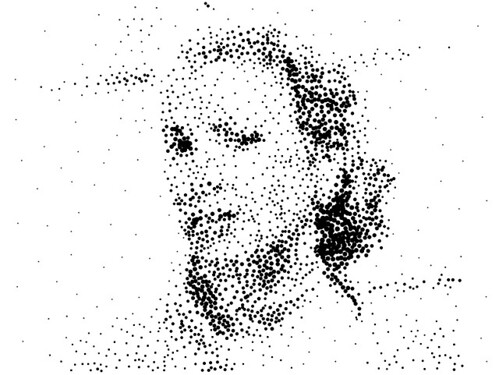
When you load a new image, the first pass of calculation begins as a crude set of points generated by rejection sampling. The number of points is controlled by the “Stipple Count” slider. Here, we’re starting with the default, 2000 stipples, and variable dot size.

After a few generations, the stipple image begins to take shape. Here, we’ve turned on the Voronoi cell display, so that you can see what that looks like.
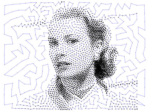
Once you are satisfied with the stipples, you can hit the “Pause” button to begin calculating the plot order, shown by the blue line here. Once that’s satisfactory, you can save the stipples to an SVG file.
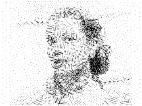
Here’s another direction to go: 10,000 stipples, instead of 2000. It takes much longer to calculate, but… sometimes, it’s worth it.
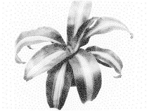
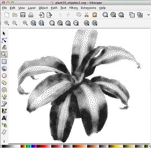
Here is another “demo file”– a corn plant, available for download from this page. This shows 10,000 stipples, with variable stipple size.
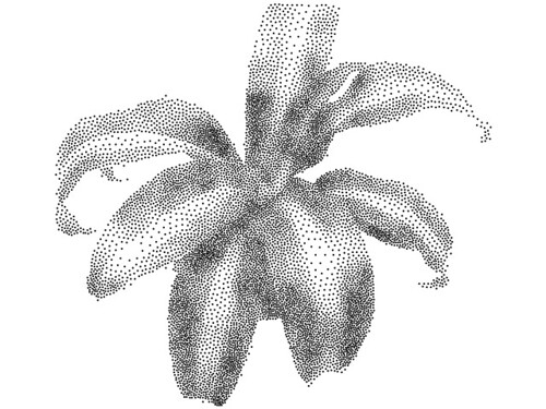
For comparison, this is what the same 10,000 stipples look like, but with fixed size. We’ve also turned on the white cutoff, so that there’s less detail away from the main plant.

When we first click the “Pause” button after letting our stipples settle, we’re presented with this mess: the path between the stipples. The blue line represents the path that a plotter would take naturally between the points. As you can imagine, nearly all of the time drawing would actually be spent moving between points.
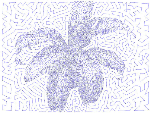
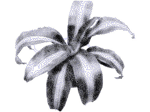
By letting this run for just a few moments, StippleGen creates a “nearest neighbor” path– a first guess at a decent solution to our travelling salesman problem. We’ve momentarily turned down the dot size so that you can see it a little better.
As you can see, there is a lot less blue on the screen here– this would plot muchfaster. One other thing to notice is that while the rare “background” dots don’t make much of a difference to the overall picture when looking at stipples, the paths between those dots at the edges are actually pretty distracting. We can invoke the “white cutoff” slider one more time to fix that, though:
Here now, we have a pretty good candidate file, reasonably well optimized.
We have now adjusted the dot sizes (both minimum and range) so that the stipples themselves are pleasing. We’ve also allowed enough time for the path to look okay for the TSP file. There area couple of stray stragglers– longer than necessary path segments that might correct themselves given time. But for the most part, it’s all good enough.
At this point, we can save SVG files– one of each, as a stipple file, and one as a TSP path.
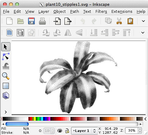
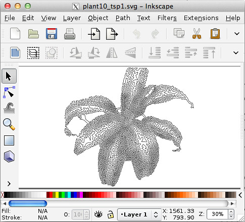
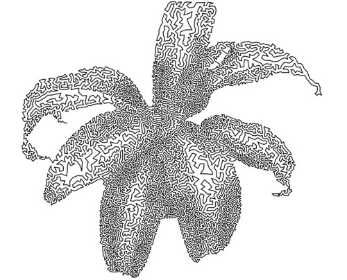
Opening up the two SVG files in Inkscape, we can see the stipple file (top) and TSP file (bottom).
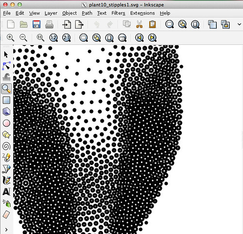
The “stipple” file is made up of many (10,000 to be specific) unfilled circles, grouped together for efficient handling in Inkscape. They’re ready to be plotted to an Eggbot or to be exported (for example) to a toolpath generator. Those circle sizes could also control hole depth with a cone-shaped wood-carving too, for example.
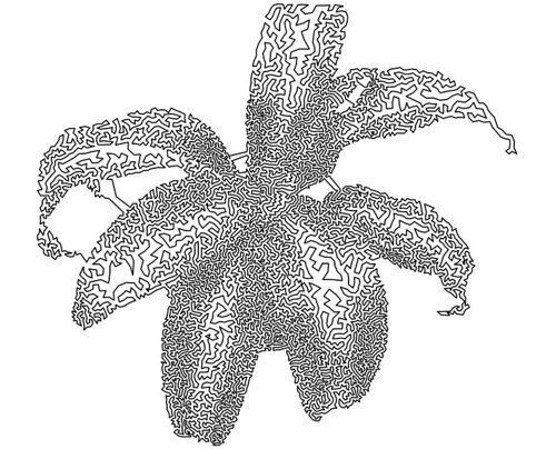
The TSP file is a single, continuous path, consisting of 10,000 nodes. We had just a couple of straggler lines in our final file (top), so we used the path tools in Inkscape to remove the offending segments (below).
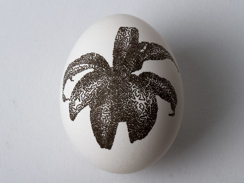
Now, to test our results on some hardware. This file plots in just a couple of minutes on the Eggbot. It’s far from a “traditional” halftone, but it’s still a pretty remarkable result.
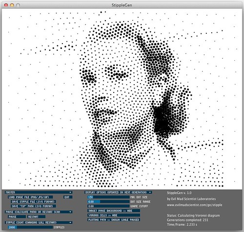
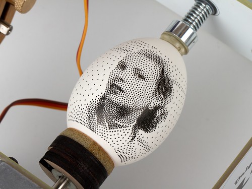
Finally, Grace Kelly graces an egg.
This image is rendered with only 2000 stipples. Properly tuned for making dots rapidly, the Eggbot can plot about four stipples per second, so this kind of a plot can take as little as ten minutes, and can actually produce a remarkable likeness of a photo onto an egg.
Credits and sources
The StippleGen source code is available as part of the StippleGen repository at github. To run the code from source, you’ll need to download Processing, and install the toxiclibs library and the ControlP5 library.
Much of the “heavy lifting” of our code is really done by the toxiclibs library. This includes the Voronoi cell calculation code, the polygon clipping code, and the code to determine whether or not a given point is within a given polygon. We were able to replace a number of complicated functions that we had written with simple library calls, without loss in performance. This is superbly useful software.
Our code also uses the excellent ControlP5 library for the GUI elements.
Thanks also to Dan Newman for helping calling attention to TSP and stipple art for use in the context of Eggbot, and particularly for documenting it on our wiki.
Additional inspiration:
• Stipple Cam from Jim Bumgardner. Our first stipple drawing code in Processing was based on this project.
• MeshLibDemo.pde A demo of Lee Byron’s Mesh library, by
Marius Watz.
UPDATE: StippleGen 2 has been released, with new features and documentation. Read all about it here!


Would the EggBot work with a wax pencil? I have fond memories of drawing patterns on eggs with white crayon, then dying them and having the patterns show up as dye-less spots and lines. I think this would make for truly beautiful stipple-portraits. The dye would bleed a little, making for an even softer boundary on the individual points.
Fantastic work EMSL! Thank you so much for sharing. I can’t wait to get home and try this out with my EggBot.
We’ve had a great instrument for a while, now we start to get easy to use music generators. What could be better?
*Brian
I kept reading the name of the software as StippleGun – which pleased me more. I offer it up as a suggestion for a name change.
Would you explain how to open the SVG file in a program like Illustrator? When I tried doing it, it just displayed XML text.
thanks
We’ve had mixed luck with SVG and illustrator– things are not always reliable going from inkscape to illustrator. My suggestion would be to open the file in Inkscape and save it as a PDF, and to open that PDF in Illustrator. (And if some kind soul who has Illustrator and knows a bit of processing can help improve our template, that would be great, too.)
Windell H. Oskay
drwho(at)evilmadscientist.com
http://www.evilmadscientist.com/
Thank you, EMSL!
This will be a lot of fun to play with in combination with my polargraph (based on Sandy Noble’s design and code).
Thanks to EMSL for sharing, this excellent sketch came up at exactly the right time for me :)
I have been playing around with an Eggbot-based polargraph*/drawbot over the last few days and I managed to get it working, at least for the TSP curve case since I don’t have a pen lift on my gondola yet…
Once I’ve got the code with the EiBotBoard serial commands tidied up a bit beyond the just-about-functional stage I’ll post it…
*I bought pulleys and cord from Sandy Noble but I’ve used Eggbot and some random junk for the rest…
Finished the code: [link: http://bit.ly/IJArJj here]
This is a draft version of some Processing code that can take a stipple SVG file from StippleGen and control an Eggbot-based polargraph/drawbot
The translation into dual polar coordinate space works & the drawing happily runs but the size of the dots from the SVG isn’t correctly scaled yet. There probably will be other errors and it shouldn’t be considered as completed code at all but it does run. I’ve a video of it running [link: http://youtu.be/a74ko5Yc8rA here] – it will draw empty or spiral-filled circles
OK, video link didn’t work – copy/paste URL if you want to see http://www.youtube.com/watch?v=a74ko5Yc8rA
Wow, this is awesome. I was inspired by Secord’s thesis a while ago and have been implementing the weighted Voronois in Processing as a learning project. It’s disappointing to be "cut off" like this, but you’ve done a great job and I’m grateful you’re sharing source and helping this algorithm live.
I’m pretty sure it toxicLIBS, not toxicLABS. :)
Really great work! Thanks much!
As regards plotting with the Eggbot, another SVG ordering for the stipples would be to draw the stipples from top to bottom vertically, then move over horizontally, then bottom to top, move horizontally, etc. Point being to minimize large horizontal excursions back and forth with a goal of reducing slippage between the egg motor and the egg itself. (’tis what I found worked best for that stipple.py script I put up.)
Dan
Hi
love the product but when i go to save it just hangs…
running osX 10.6.8 2×2.66 GHz dual core with 4gb ram
You might consider running the sketch from within Processing, to see if that helps. Also, consider updating your Java to the latest version. FWIW, the program was written on a Mac, and we haven’t seen this issue ourselves.
Windell H. Oskay
drwho(at)evilmadscientist.com
http://www.evilmadscientist.com/
Any suggestions on how to optimize an image for stippling? Convert to B/W, increase/decrease contrast/… That sort of thing?
Thanks.
An image that looks *good* in grayscale is a good candidate, and that’s the main criteria that I’ve used in choosing sample images.
Windell H. Oskay
drwho(at)evilmadscientist.com
http://www.evilmadscientist.com/