Tag Archives: electronics

Open Circuits: Now available

Earlier this year, I wrote about my then-forthcoming book, Open Circuits: The Inner Beauty of Electronic Components, co-written with our regular collaborator Eric Schlaepfer.

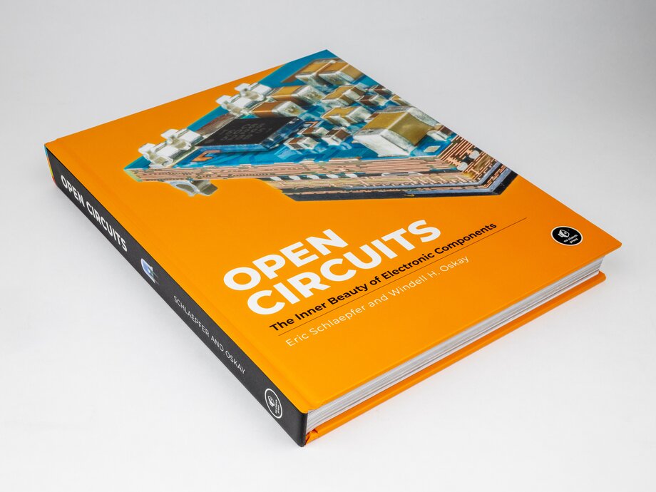
Open Circuits is a coffee table book full of close-up and cross-section photographs of everyday electronic components. And, it’s now shipping! As of today, it’s available in hardcover from your local bookstore, as well as to purchase online and in electronic versions.

Open Circuits, hardback

We also just launched a new website for the book, with links of where you can purchase it as well as lengthy galleries of images from the book and of outake photos.

We put up a list of sellers on the website, including direct from No Starch and our own store, where signed copies are available.

Open Circuits

I’m very pleased to announce my forthcoming new book, Open Circuits: The Inner Beauty of Electronic Components, co-written with Eric Schlaepfer.

Open Circuits is a coffee table book full of cross-section photographs of electronic components, along with photos of those components in context, and descriptions of how they work. It’s coming this fall from No Starch Press, and is available now to pre-order.

Book cover for Open Circuits

From the rear cover:

Open Circuits is a photographic exploration of the surprisingly beautiful design waiting to be discovered inside everyday electronic devices. Through painstakingly prepared cross-sections and stunningly vivid close-up images, the book reveals a hidden world full of elegance, subtle complexity, and wonder. From simple resistors and capacitors, to cutting-edge circuit boards and retro Nixie tubes, the authors’ arresting imagery transforms more than 130 electronic components into awe-inspiring works of art that will delight engineers, artists, designers, and photography enthusiasts alike.

My co-author Eric Schlaepfer has been our regular collaborator on projects such as the Three Fives and XL741 soldering kits, as well as the MOnSter 6502 and our Uncovering the Silicon project.

Open Circuits is coming this fall in hardcover, and is available now with a pre-order discount and early-access PDF from No Starch Press.

It’s also available to pre-order at your local bookstore — who we sincerely encourage you to support — as well as Amazon, Barnes & Noble, and other major booksellers.

The 555SE and 741SE surface-mount soldering kits

555SE and 741SE kits

Today we are pleased to announce the release of two new soldering kits: the 555SE discrete 555 timer and the 741SE discrete op-amp.

Both of these new kits are surface mount soldering kits — our first surface mount soldering kits — and we think that you’re going to love them.

555 kits, big and small

You might be familiar with our Three Fives discrete 555 timer and XL741 discrete op-amp kits. Both are easy soldering kits that let you build working transistor-scale replicas of the classic 555 timer chip and the famous µA741 op-amp. Those two are constructed with traditional through-hole soldering techniques and are styled to like “DIP” packaged (through-hole) integrated circuits.

Our new 555SE and 741SE kits implement the same circuits, now with surface mount components, and are styled to look like smaller “SOIC” packaged (surface mount) integrated circuits, complete with a heavy-gauge aluminum leadframe stand. Side by side with their through-hole siblings, the new kits are exactly to scale, with half the lead pitch and a lower profile.

555SE kit for scale

The 555SE and 741SE kits each come with eight (tiny) color-coded thumbscrew binding posts that you can use to hook up wires and other connections.

You can also probe anywhere that you like in these circuits — something that you generally can’t do with the integrated circuit versions.

741SE kit close up

The new 555SE and 741SE circuit boards are black in color, with a gold finish and clear solder mask so that you can see the wiring traces between individual components. There are a few other neat details here and there, such as countersunk holes for mounting the board to the leadframe.

The surface mount components are relatively large, with 1206-sized resistors and SOT-23 sized transistors, and assembly is straightforward with our clear and comprehensive instructions. These kits are designed to be a joy to build, whether you’re an old hand at surface mount soldering, want some practice before tackling a project, or are introducing someone to it for the first time.

Family portrait

And here is the new family: XL741, the Three Fives, along with the new 741SE and 555SE.

You can find the datasheets and assembly instructions for these kits, as well as links to additional documentation, on their respective product pages.

Both new kits are part of our ongoing collaboration with Eric Schlaepfer, who we have worked with on a number of dis-integrated circuit projects including the four kits here and the MOnSter 6502.
Basics: Base Resistors on Transistors

highside-good

Our reader Jon wrote in with a question about our open collector tutorial:

I really appreciated the tutorial, and I was able to follow along and understand it very well. One question I had was – what is the purpose of the 1 kilo-ohm resistor that is connected to the base of the PNP transistor? Because when the open collector is ‘high’ then the base of the transistor is at 12 V and it appears the 1 kohm resistor didn’t affect anything, and then when the open collector goes ‘low’ then the base is connected to ground through the output of the SN7407. So basically, what would the difference be if there was no 1 kilo-ohm resistor at all?

And, that’s actually an excellent question, about something that we usually gloss over.

The short answer is that this is a “base resistor” that we use to limit the maximum current that flows through the base of the PNP transistor.  But, let’s take a look in a little more detail, and see what would happen if we didn’t have that there.

Continue reading Basics: Base Resistors on Transistors

Inside the ULN2003

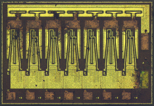
Over at ZeptoBars, they have an incredibly detailed “take-apart” post on what’s inside the ULN2003 seven channel Darlington driver chip. The ULN2003 is commonly used for driving LED displays—you can find it, for example, in our Mignonette game.

We often receive comments that while out microchip photos are beautiful and interesting, it is completely unclear how integrated circuit implements basic elements and form larger circuit. Of course it is impossible to do a detailed review of an 1’000’000 transistor chip, so we’ve found simpler example: ULN2003 – array of Darlington transistors.

They’ve stripped off the outer housing and put it under the microscope. They then analyzed the photos to show you what parts make up the individual transistors, resistors and diodes inside the chip.

The Mug Marker

Untitled

Untitled

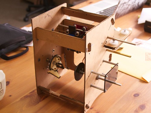
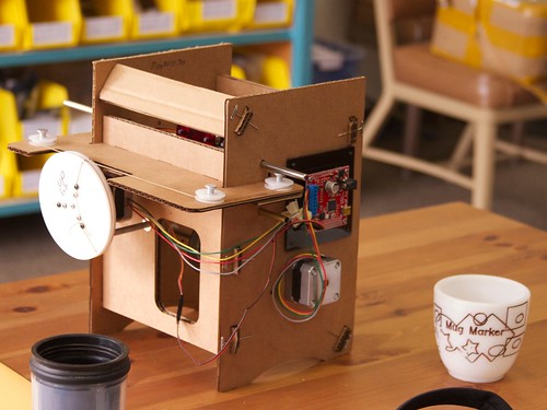
Don McRae recently stopped by our shop last week to show off his homebrew CNC project, the “Mug Marker” — a wonderful little cardboard robot that can draw on mugs.

Much like the Mug Plotter on Instructables, it uses the same EBB controller board and stepper motors as the Eggbot, but with linear motion for the pen instead of rotation. However, unlike that version, Don has incorporated the same winch-drive mechanism that we use on the WaterColorBot to provide motion for the linear axis– meaning that it can go fast or slow, with very good accuracy.

Don laser cut the large white winch on the back of the machine from acrylic. It controls a string that pulls the pen carriage back and forth as it rides on a pair of rods:

Untitled

Untitled

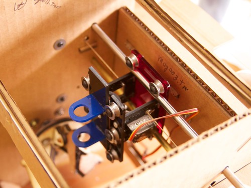
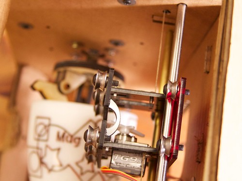
The pen holder itself slides into some additional bearings, and has a small protrusion on the back that rests on the servo horn, allowing it to be lifted up or lowered down.  Like the Eggbot’s pen-lift mechanism, this mechanism only (actively) lifts the pen, which means that it can ride over uneven surfaces, or plot on mugs with variable diameter.


Untitled

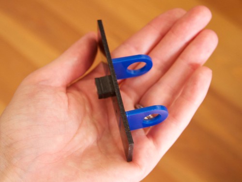
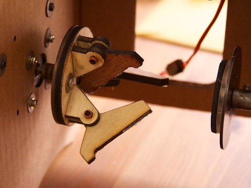
Underneath the pen carriage, the opening of the mug fits onto a three-jaw coupler on the motor shaft, and the base of the mug is held against a rubber faced spring loaded plunger. Small copper tubes are used as bushings to allow the coupler pieces to rotate inward or outward to allow mugs of differing diameters to fit on. A little silicone on the surface of each of the three parts provides a gripping surface, and the upcurved lip keeps the mug from sliding too far.

Untitled

Looking down through the pen carriage, you can see the mug below held in the coupler.

Untitled

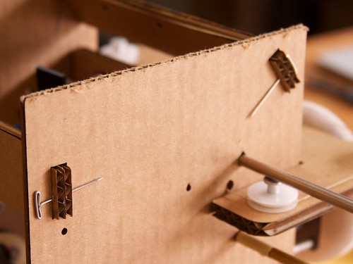
The chassis of the machine is made from cardboard, either hand or laser cut to slot together, and held together very cleverly with pins. The whole machine is put together from a combination of off the shelf parts and found materials, many of which are laser cut for the correct shape. For software, Don uses the Eggbot Inkscape extensions with very reproducible results.

Thanks to Don for bringing it by and letting us take pictures!

Oddities at the Electronics Flea Market

eFlea July 2013

Today was the monthly Electronics Flea Market in Cupertino, and we came across some gems this month.

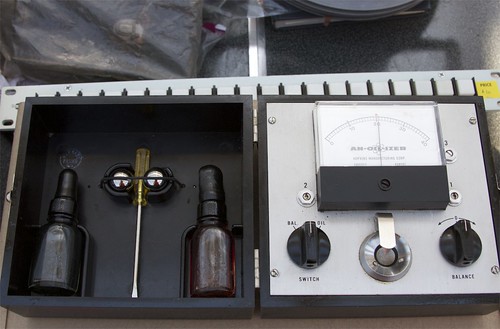
Above, an AN-OIL-IZER. The seller said her geologist father used it for testing oil purity.

It’s described in patent number 3182255, a device for capacitively testing lubricating oil (e.g., engine oil) for contaminants, by looking for changes in its dielectric constant. To use it, you place a drop of the oil in the holder, and the ball bearing into that drop of oil.  The bearing is held down by a leaf spring, keeping it indexed against the holder.  This forms an oil-filled capacitor between the ball bearing and a lower curved plate that is insulated from the bearing. The capacitance will vary as the dielectric constant of the oil changes due to contamination.  It comes with two ball bearings, as well as oil samples for calibration.

eFlea July 2013

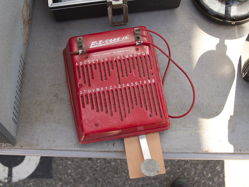
The E-Z-Code Jr. is a tool for learning morse code: when you draw the “electric pencil” through the slots, it crosses contacts in the correct spacing to make the characters. It also has a hinged telegraph key which can be tucked away below the device.

eFlea July 2013

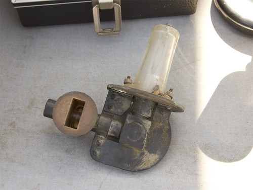
The seller of the E-Z-Code Jr. told me that the thing I really should be photographing was this magnetron. It is a beautiful old piece of hardware, with its wave guide and high-power tube.

eFlea July 2013

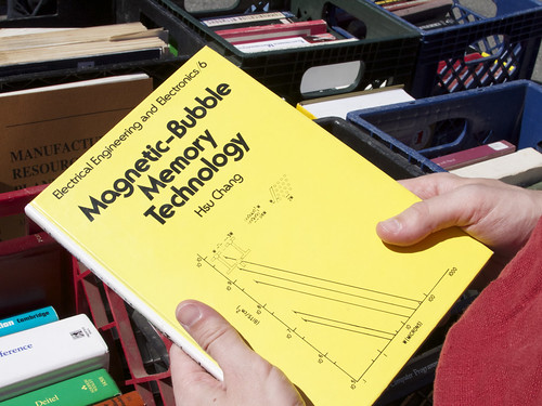
We found a book on Magnetic-Bubble Memory Technology. We also saw a book on tube delay memory.  We’re not sure if these are a step up from the single-bit flip-flop memory in our Digi-Comp II.

eFlea July 2013

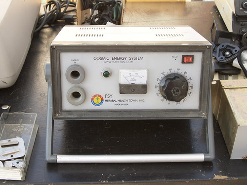
I’d love to see the circuit diagram for the Cosmic Energy System by Psy Herabel [sic] Health Town, Inc.!  (Sadly, their domain no longer seems to be active.)