The last decade has seen more than an order of magnitude drop in the price of
accelerometers, devices capable of measuring physical acceleration (often in more than one direction). History suggests that whenever a useful technology makes a precipitous drop in price, unexpected applications follow, and that’s exactly what has happened in this case.
Starting from zero and summing up acceleration, you can use an accelerometer to find velocity, and from that derive relative position information. By measuring the acceleration due to gravity, one can also determine orientation (technically, inclination)– you can tell which way it’s pointing. Those are pretty useful skills for a chip! And so as bulk prices for tiny chip-scale three-axis accelerometers have begun to approach $5, they have started to appear in all kinds of mass-market applications that you might not have predicted: laptop computers (for hard drive protection), smart phones and cameras (for orientation– e.g., portrait vs. landscape on the iPhone), cameras for image stabilization, and quite visibly in the controllers for Nintendo’s Wii system.
With all that promise, you might think that an accelerometer is a difficult beast to harness. That turns out not to be the case. In this little project we demystify the mighty accelerometer and show you how to get started playing with one. In the spirit of hobbyist electronics we do this the easy way– without designing a PCB or even soldering any surface-mount components.
Note: An updated version of this article is now available here.
Our project consists of two main elements: the accelerometer chip and a microcontroller that will read out the data and display it. Let’s first focus on the accelerometer. We’ll be using the ADXL330, which is a very popular little XYZ accelerometer made by Analog Devices. It’s actually the same chip that you would find as the accelerometer inside the Nintendo Wiimote controller. Purchased one at a time, on its own, this chip costs about $11.50 from Digi-Key, and the price goes down to about $7.25 in large quantity. (If you are Nintendo, the price is even lower.) One of the downsides to new and fancy devices like these is that they tend to come in unfriendly packages. The ADXL330 is only available in a 16-pin LFCSP; that’s a plastic package 4 mm X 4 mm, with pins that can be seen through a good magnifying glass. While it’s hard to work with on it’s own, there actually is a good solution for playing with this: get a breakout board.
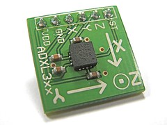
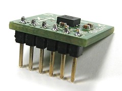
This breakout board from SparkFun comes complete with a ADXL330 accelerometer soldered in place. The relevant connections to the chip are broken out into a row of 0.1″ spaced holes (which I have filled in with a six-pin header) and the three sensitivity axes of the chip are clearly labeled with bright markings on the silkscreen layer– a nice touch. The board is Sparkfun SKU#: SEN-00692, $35. Yes, it costs a fair bit more than the bare chip itself, but the price is fair and the convenience factor can’t be beat.
(If cost really is an issue, one potential option is to actually use Nintendo’s buying power to your benefit: disassemble a wii nunchuk controller ($20) to get at the similar accelerometer that lives in it. You could even take apart the Wiimote itself, if you can get a good price on the unit. In any case, getting at the connections to the chip will be much more difficult than just buying a decent breakout board.)
The accelerometer actually has a very simple analog interface. We only really need to connect to five pins on it. First, it wants power. It needs 1.8-3.6 V (and ground), and just to keep our discussion simple, let’s plan on using 3V for everything– either use a single lithium coin cell two alkaline AA cells in series. The chip also has three analog outputs– one for each direction. On these outputs, 1.5 V (really, halfway between the power and ground rails) represents zero acceleration, and deviations from that, either higher or lower, represent higher or lower accelerations.
The chip is sensitive to accelerations of +/- 3 g in each direction. (There is a sixth pin on the breakout board, which is for a self-test feature on the ADXL330 that we will not be using.)
Next, we need a simple microcontroller to read out the analog outputs and process them. We’re using the Atmel ATmega48, a member of the ATmega48/88/168 series of AVR microcontrollers. If you’re new to programming AVR microcontrollers, you have an extra step and some reading to do here. (And, as it turns out, this actually *is* an excellent example of a “first” microcontroller project for anyone.) To get up to speed, please read LadyAda’s tutorial. As is explained in the tutorial, you will need an AVR programmer (e.g., USBtinyISP, $22) and a working installation of the (free) AVR software toolchain.
Now we come to actually building up the hardware. The first step is to build a simple target board for the ATmega48; a board on which the chip can be programmed. As explained in that article, we need a socket for the AVR (28-pin 0.3″ DIP), a 6-pin DIL header, a battery holder (in this case lithium coin cell or 2 X AA), and a piece of prototyping perfboard to build it all on. Besides those, we also have the accelerometer breakout board, of course.
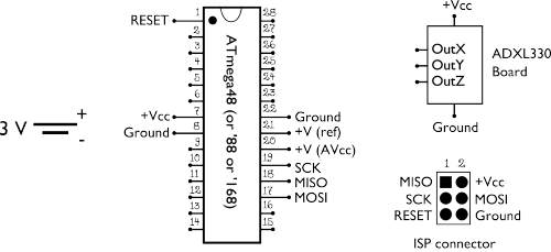
From the battery (left side) we hook the postive end to the indicated pins (+Vcc, +V) of the microcontroller (3 places), the ISP header, and the ADXL330 breakout board. The negative side of the battery is our effective ground, and get wired up to the ground pins of the microcontroller (2 places), the ISP header, and the ADXL330 breakout board.
The four remaining pins on the ISP connector (the 2 x 3 header) also need to be wired up to the matching pins on the microcontroller: MOSI, MISO, SCK and RESET.
We have skipped drawing the wires here to keep the diagram from looking like this. Hopefully, you learned connect-the-dots long before soldering. :P
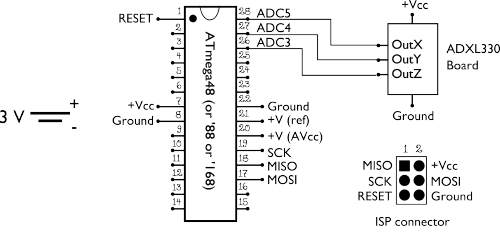
Next, wire up the outputs of the ADXL330 board to the ADC inputs of the microcontroller as shown. X output to pin 28, Y to pin 27, Z to pin 26.
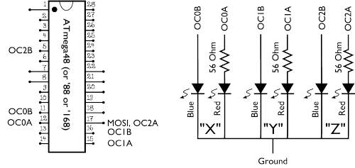
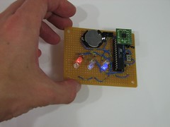
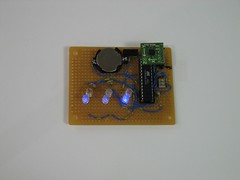
Finally, we add some indicators: two LEDs (one red, one blue) for each of the three axes. The big idea is that when there is no acceleration in (say) the X axis direction, both LEDs are off. When it detects acceleration one way, the red LED lights up (and lights up more, the harder the acceleration is) and it lights up blue for acceleration in the opposite direction. (Naturally, the other two axes work the same way.)
To do this, we’re using the pulse width modulation outputs from the three timers (timer 0, timer 1, and timer 2) on the microcontroller. Each timer has two outputs, called “output compare” pins A and B, which go to the two LEDs. The six outputs are called OC0A, OC0B, OC1A, OC1B, OC2A, and OC2B, and are hooked up to the LEDs as indicated in the diagram.
The AVR can directly drive LEDs of either color, without a series resistor, when powered by a lithium coin cell. However, it turns out that the AVR cannot be *programmed* in the circuit if the red LEDs are hooked up as shown but without the series resistors. (That’s because of the difference in LED forward voltage for the two colors.) If you use an alkaline battery to run this circuit, you may wish to put a small resistor (~30 ohms) in series with the blue LEDs as well.
 Two minor details, not shown in the diagrams. First, the ADXL330 breakout board is socketed– I cut apart a dip chip socket to make a holder for the breakout board 6-pin header so that it doesn’t have to be permanently soldered to this setup. Secondly, I added a small power switch by the battery holder that lets you switch the circuit on or off easily.
You can download the firmware program (C code) for the AVR here (11 kB .ZIP file). It’s a very simple AVR-GCC program, licensed under the GPL. It reads in three analog
inputs sequentially, and lights up the six display LEDs depending on the values that it reads.
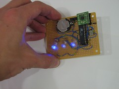
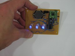
Once you’ve gotten the AVR programmed, it should be ready to go and show you outputs that depend on the acceleration. As you swing it around, even fast, you can see the LEDs responding to motion in the different directions.
If you aren’t wildly swinging the board around, what you’ll see is just the steady-state gravitational acceleration displayed. You might call it a precision tilt sensor, and it can tell you which way is up.
If we tilt our board left or right, such that the X-axis is now pointing slightly up or down (slightly with or slightly against gravity) you can see the X-axis LED pair, which is the on the left, switch from red to blue:
If instead we tilt the board forward and back, such that the Y axis is along or against gravity, you see the same thing for the middle pair of LEDs:
Finally, the Z indicator pair, on the right, is blue until you turn the board upside down– or shake it up and down.
So that’s it: a working “Hello world” for an accelerometer, all the way up to blinking LEDs.
Our C code is intentionally simple, and ready to mod. What can you do with it?
Soon, your little homebrew robot– or maybe gigantic evil death machine– will be able to tell how far it’s been, which way it’s facing, and which way is up. We think that this a useful building block, and we’ll be interested to see what other new things people build with it.
Note: An updated version of this article is now available here.



Good job, there are not too many accelerometer interface articles out there.
I have a question, is this accelerometer able to be used for vibrational measurements?
You say "As you swing it around, even fast, you can see the LEDs responding to motion in the different directions."
I am currently designing a system that records wheel flats on railway wagons, and was wondering if such a system would pick up such a vibrational anomaly? Can you describe the amount of movement required to change the LEDs?
A video of you shaking your system around (slow, easy – fast, hard) would be awesome!
Dino
You certainly could use the accelerometer for vibrational measurements. The particular response of the LEDs is really easy to change and if you wanted to, you could make the display much more sensitive than I have here.
—
Windell H. Oskay
drwho(at)evilmadscientist.com
http://www.evilmadscientist.com/
Excellent, thats great.
This could help me in my endless quest for stabilized video from a bicycle mount. Is there any way to take the +- 3V and drive a 6-12V linear actuator with fast smooth motion? If so then I could get rid of all my aluminum arms bearings, springs, Too cool. Thanks
That certainly could be done. The chip output is 0-3 V, by the way (or +/- 1.5 V from 1.5 V), not +/- 3 V.
What kind of a drive depends on what type of actuator you’re using, but it doesn’t sound like a big challenge to do what ever kind of level translation and high-current buffering you might need.
—
Windell H. Oskay
drwho(at)evilmadscientist.com
http://www.evilmadscientist.com/
Great work first all. By the I’m working on my final year project making use of DsPIC P30F6014A to read in analogue outputs of the adxl330 x,y,z pins. I got few questions though?
1) what is the best reference voltage that can be chosen for DsPic P30F6014A when interfacing adxl330 to get better results
2) The out impedance of adxl330 is 32k,PIC & Atmel processors require 10k or less. How did you go about this? Some suggesting using OPAM non-inverting.
Your help is very much appreciate. Email me at keleistein@yahoo.co.uk
1) Use a voltage reference chip. TI makes a number of good ones, for example.
2) The Atmel chips do not "require 10k or less," they just recommend it for fastest response, and in this context 32 k is not far from 10 k in any case.
—
Windell H. Oskay
drwho(at)evilmadscientist.com
http://www.evilmadscientist.com/
for your case you seem to have used 3volts for your reference voltage. Did you connect your vref- to the ground?
How about deriving 3volts using voltage divider, are there any complications?
How do you convert the adc values to Gs? any idea?
Thanks
The data sheet specifies the number of mV/g of acceleration.
—
Windell H. Oskay
drwho(at)evilmadscientist.com
http://www.evilmadscientist.com/
I now have some useful data from adxl330 accelerometer and would like to automatically determine the damping ratio of the signal. This signals are obtained when my accelerometer is connected to a trolley drop from a bump. when plotted on excel, the signal represents a decaying signal.
How can I accurately determine damping ratio from this signal using microprocessor? any idea?
Regards,
sk
Well, if you can write a function for it in Excel, you can do the same on your microcontroller. Is there a specific problem?
—
Windell H. Oskay
drwho(at)evilmadscientist.com
http://www.evilmadscientist.com/
Th formula I would used in excel for determining damping ratio is as follow:
theta = Ln(A1/A2) :where A1 and A2 are amplitudes or successive peaks of the signals;
damping ratio DR:.
DR: = theta / sqrt(theta*theta + 4*PI()*PI())
How can I implement this on a microprocessor given the signal from an accelerometer from a car moving over a bump at 5kph
Do you think this might as a controller for a camera on an oscillating platform?
In other words wait till x, y, and z motions all drop below a variable threshold to fire a signal to the shutter. A little bit more complicated might be a predictive algorithm that triggered the camera a little earlier (for auto shutter speed, f-stop, exposure compensation, etc.) before the motion minimum. Better yet with information from angular rate sensors too.
I’d love to do the above ^ and add on a data-logger for accelerometer data (and perhaps GPS). Any ideas?
Actually, you want the acceleration to be steady– indicating that you’re resting on a stable platform, rather than to be zero– indicating that you’re in free fall, and about to go SMASH!
—
Windell H. Oskay
drwho(at)evilmadscientist.com
http://www.evilmadscientist.com/
Good point. My camera’s on a damped pendulum 100 meters up and I’m only really thinking about x and y. I think about z but that’s more about property damage and bodily harm.
Anyway I think I’ll give it a try.
hi there…
actually i was thinking of initiating a project on “robotic-arm”
where the arm will emulate my hand and finger’s movement.
what i wish to know, can i get 5 degree of freedom sensing through one accelerometer chip…ie using only one chip, is it possible to sense the motion of my wrist and my fingers.
Hi,
Id like to save all data of accelerometer into a memory SD could you help me about that?. Is it same circuit with several modifications?.
Yhanks.
Please could you answer me to davidarrabal1981@hotmail.com
That would be a pretty major change; you could use our example code as a snippet to make that work, but it’s really much more involved.
—
Windell H. Oskay
drwho(at)evilmadscientist.com
http://www.evilmadscientist.com/
hello
please send me some project with avr ,using ADXL330.
may email: fatimah_61@yahoo.com
thank you very much.
bye.
hello
please send me some project with avr ,using ADXL330.
may email: fatimah_61@yahoo.com
thank you very much.
bye.
Hi, I downloaded the C code and can’t open it …
Is it possible for you to share the C code in a notepad file so I can open it ?
Thanks alot
Excellent stuff! Keep it up!
Hi,
Thanks for this excellent tutorial. It’s my first try on an AVR and I managed to get it working (amazing), but can’t figure one thing out; The led’s dont show any difference between soft shaking and hard shaking. Ive previously made a setup with an Arduino and Nunchuck (which is eventually the same hardware as this tutorial, if I understand well) and that gives a very nice difference between soft and hard shaking.
Should this setup do that as well, or would it be able to?
I have no experience in C so have a hard time trying to understand and reconfigure the script, so any clues to where to look and how to amend which part of the code would be much appreciated.
Also another question, would it be a problem to run this on 4.5V or more? I’d like to get more light out of it.
Many thanks!
When built correctly, this project should give smoothly changing LED output– able to detect and display small angles.
—
Windell H. Oskay
drwho(at)evilmadscientist.com
http://www.evilmadscientist.com/
Hi,
Thanks for your reply. I didn’t mean the transition is not smooth – the brightness changes very smoothly when tilting the device, which strength I was also able to amend in the code with the (originally) 2* multiplier.
What I meant though is acceleration, instead of tilt. If I suddenly move the device straight up, it does give a quick flicker, which is always the same, where as in the Arduino setup the sudden move up is noted much more detailed, and there is a difference in brightness levels with upward moves of different intensity. I hope I’m being clear?
Sounds like a software difference. This program gives real-time output, with no averaging or smoothing. Look at the algorithm used in the other one, if you want to replicate that behavior. "Arduino" is not really different from "AVR" — the same code will run on this processor whether you give it a new brand name or not.
—
Windell H. Oskay
drwho(at)evilmadscientist.com
http://www.evilmadscientist.com/
hello im working with ADXL 330 TO MONITOR THE HUMAN ACTIVITY . PLEASE HELP BY GIVING IDEA ABOUT HARD WARE DETAILS
peter_ece1987@yahoo.com
hello friends!
i have question, can i measure distance of one point to end point by ADXL330?
if your answer yes , how can i?
do i integrate twice from accelaration?
please help me…
i would this module in submarine to measure distance…
Hi there,
I’m looking into intigrating the adxl330 chip into my L3 university project. What I need to know is can the chip sense when it is being twisted/spun around? Ie, it is flat on a surface and twisted/turned as if there was a pivot in the middle of the chip. I hope this explanation makes sense :)
Thanks
Tony
No. What you’re looking for is called a "rate gyro" chip.
—
Windell H. Oskay
drwho(at)evilmadscientist.com
http://www.evilmadscientist.com/
HI
part of my project involved using the accelerometer to connect to the PIC16f877 so that we can read the acceleratio for 3-axis (X,Y,and Z) from the PIC16f877 to pc.
if You have the code to reading of the data
I would be very happy if will be able to send me the code
And also if you have the circuit of the connection pic to adxl330.
thank you
nachum.adi@gmail.com
This is most interesting. Do you know the resolution values for the various acc chips available.
If one were to use 1 vs 10 vs 50 chips in an array, could you increase the resolution (accuracy) of the readings. I am interested in measuring gravity to a high degree, perhaps 10^-8 of 1G, typical for gravity meters.
The iPhone uses an ST LIS331DL chip: +-2g but if I read the specs right, it only has 8 bits so that’s 128 parts per 1g, not a great resolution. If I read that as bad, then it might take a truck load to get down to what I’m looking for.
Is there anything more accurate?
>Do you know the resolution values for the various acc chips available.
The sensors are analog. The bit resolutions that we discuss are internal to the microcontroller and are unrelated to the sensor outputs.
—
Windell H. Oskay
drwho(at)evilmadscientist.com
http://www.evilmadscientist.com/
Hii
Thanks for a great articles on accelerometers for beginners. Well there is a problem that i want to discuss. Is it possible to note the reading of a point for instance (x=6, y=5 and z=2) through an accelerometer.
Actually i am working on a project in which a robot can note the reading of a point and save it in the micro-controller and then it can visit the point again when commanded.
Any guidance regarding this will really help me.
Thanks
Unless you had some very strong gravity-generating material at the origin of this plot, this particular chip wouldn’t be able to tell you where a point in space is/was. It can tell you which way in all three dimensions the chip is tilting, but it can’t give you relative distances from an origin.
Well, okay, I take that back. In the very first part of the article, it discusses that you can calculate velocity and then distance based on acceleration, but I wouldn’t exactly call it "easy" to do in a small robot, IMHO.
So is there any way that we can get the coordinates of a point in space? Although the space will be limited like (-10 to 0 to 10). Or is there any other sensor or perhaps some logic of the algorithm that can be programmed into the controller.
Secondly i cant figure out the above C program for the AVR controller. I think i m a bit weak in C controller programming. so can you please just share us the step by step logic that’s being used in the program, so that i can program it for PIC or 8051 in assembly.
& Thanks for your help
"So is there any way that we can get the coordinates of a point in space?"
The short answer (again): No.
"Although the space will be limited like (-10 to 0 to 10). Or is there any other sensor or perhaps some logic of the algorithm that can be programmed into the controller."
If you have a robot that is programmed to move to a specific place, and then move to another point based simply on coordinates, all you need to do is keep track of the coordinates of where you start, and then move to where you want to go. If you’re at 0,0, and want to move to 2,0, you program the bot to move to 2,0, and then it stores the fact that it’s at 2,0. To move to -5, -8, the bot would need to move -7 units X and -8 units Y. Repeat ad infinitum.
You can’t use an accelerometer to figure out where you are on that grid. You just keep track of it as you go along (at a basic level)
Thanks for ur reply. i got it this time, Can you please simplify the above program made in C. I mean please just tell us the logic behind this program. Well i think is that the accelerometer gives a pulse every time its tilted in any direction. So the controller is programmed so that when ever the accelerometer readings go high they send a pulse to the led’s. Am i right? and how do u program it for the strong led blinking, so that when the accelerometer is tilted powerfully the led’s too light-up strongly.
I’m not sure how to answer this. You say, "Is it possible to note the reading of a point for instance (x=6, y=5 and z=2) through an accelerometer." The accelerometer reads *acceleration* — not "points" whatever those are. If you mean, "can an accelerometer measure where in space it is?" The answer is simply "no."
Windell H. Oskay
drwho(at)evilmadscientist.com
http://www.evilmadscientist.com/
Hi,
I was curious about this as well, as I am constructing a similar project. I see that you had labeled the microprocessor with three input pins and three output pins, to represent the X, Y, and Z planes of the one accelerometer. But I also saw unlabeled pins. Are there more input pins and output pins that can handle more accelerometer chips? If not, is there another microprocessor that could?
Any advice you could give on this would be greatly appreciated.
Thanks
>[…]you had labeled the microprocessor with three input pins and three output pins,
>to represent the X, Y, and Z planes of the one accelerometer.
The X, Y, and Z labels are only on the accelerometer outputs, not on the microcontroller inputs.
>But I also saw unlabeled pins. Are there more input pins and output pins that can
>handle more accelerometer chips? If not, is there another microprocessor that could?
I’m not sure why you’d want output pins for this. There are six analog inputs on this particular AVR, so you can read out the complete output of two accelerometers. Other AVRs, and other microcontroller types as well, sometimes have more or fewer analog inputs.
Windell H. Oskay
drwho(at)evilmadscientist.com
http://www.evilmadscientist.com/
Would you happen to know of a particular model that has 15 (or more) inputs – to handle 5 accelerometers?
Thanks again for your input. This has helped tremendously.
You might look at the xmega chips; some of them have up to 16 accelerometers. We recently wrote about them here.
Windell H. Oskay
drwho(at)evilmadscientist.com
http://www.evilmadscientist.com/
it’s nice work and help for bigener, maybe my q is stupid little but what "g" mean in ((+/- 3 g in each direction)) gradient ?, if so then it’s like +/-2.7 degree ?
1g = the average force of Gravity on the face of the Earth; approx. 9.8 m/(s^2)
thank u, can u plzz give me any link talk about those sensors and them work and what connection and deferences in work between accelerometer and rate gyro and how they used together any link or information will be highly appreciated thank u very much
hi…i m making a Gesture Vocalizer using microcontroller base.
in this project we do not get tilt senser..
so i will use this senser..
plz reply
im desiging a pedometer using this accelerometer. any ideas on how to compute the distance and work expended when you the device and walk
can we use ADXL330 for monitering earthquake vibration, for practical porpose can we use mobile vibration to check its working.
Yes, but it’s not a calibrated instrument like a seismometer. The value as a scientific instrument only comes from monitoring many devices in a distributed manner.
Windell H. Oskay
drwho(at)evilmadscientist.com
http://www.evilmadscientist.com/
thank you