Last year David Friedman published on his blog Ironic Sans an interesting design concept for something that he called The Bulbdial Clock.
That’s like a sundial, but with better resolution– not just an hour hand, but a minute and second hand as well, each given as a shadow from moving artificial light sources (bulbs).
We’ve recently put together a working bulbdial clock, with an implementation somewhat different from that of the original concept.
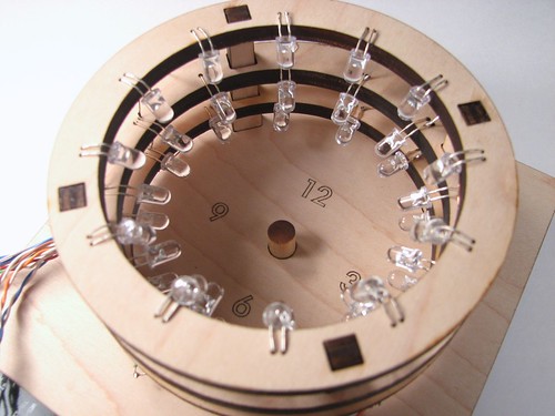
Rather than using three physically moving light sources at different heights, we use three rings of LEDs at different heights. Within each ring, we only turn on one LED at a time, so that we only have a single effective light source– it can light up at different places from within the ring. The three rings are located above one another so that they each project light onto the rod in the middle, making shadows of different lengths.
Additionally, for fun and clarity, we used red, green, and blue LEDs for the three rings, making each shadow hand of the clock a different color. Each ring has 12 LEDs, and the 36 LEDs are efficiently multiplexed by an AVR microcontroller that also handles the timekeeping part of the project.
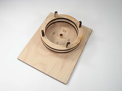
This clock is mostly built out of laser-cut plywood.
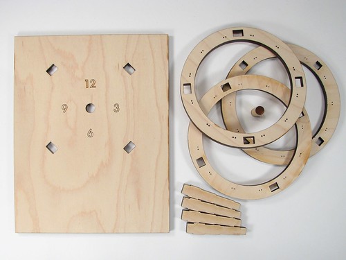
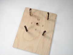
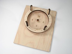
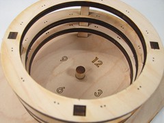
This is 1/4″ (6 mm) plywood, which holds remarkable precision with the laser cutter. There are three rings, shaped spacers that keep the rings above the base with the clock face, and a hardwood dowel rod.
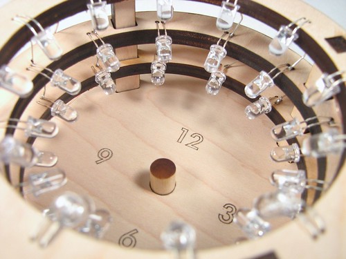
It’s really quite a three-dimensional project! The rings each have pairs of small holes in them to mount the LEDs in place.
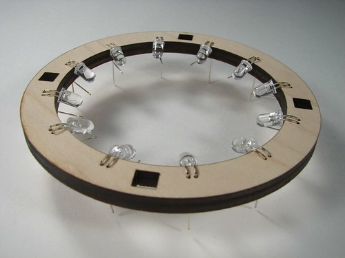
Each of the rings gets stuffed with 12 LEDs, with the correct orientation and spacing– long enough leads– that they can point towards the rod (and make good shadows) once they are in place.
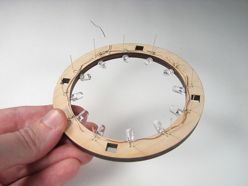
Since each LED is only supposed to be on one at a time, we can drive the whole array pretty easily, and directly from the microcontroller, Here we are turning this array of LEDs into a single common-anode unit, by hooking all of the LED anodes together. Likewise, after we stack these, we connect the cathodes — vertically for the three rings– and hook those up to the microcontroller as well. For three rings (colors) and 12 cathodes, that means that we need 15 pins to control the array.
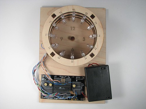
The next step is to add the control electronics. I used one of our business card boards, an ATmega168 microcontroller (programmed through a USBtinyISP), along with a 16 MHz crystal oscillator, a 3xAA battery box with switch and three tactile button switches. Not to mention a snarl of wire. There are also three resistors, two 50-ohm and one 100-ohm, which are used when driving a red LED, or blue or green, respectively. Because only one LED is on at a time, we only need one resistor for each color.
Of the three buttons, two are used for setting the time– one is fast advance, one is slow advance. The other button turns on or off the LED, but does not turn off the microcontroller. When the LED is on, the circuit uses about 26 mA of current. When the LED is off– just timekeeping, not displaying — it uses about 11 mA. These could both be reduced by using larger resistors and reducing the speed of the microcontroller.
(Aside: These parts were chosen principally for being the ones lying around. However, they’re mostly the right kinds of thing. The microcontroller is about the right size for the number of pins that are needed for this project, but we probably could have gone with one that had less memory– the control program is pretty small. A quartz crystal oscillator is nice because it’s *a clock* and shouldn’t lose much time. But 16 MHz is much faster than is needed, and the power consumption of microcontrollers depends on clock speed, so I’d pick (maybe) a 1 MHz crystal next time. The battery box is actually just right– 4.5 V provides comfortable headroom for driving blue and green LEDs, but not too much, and AA cells give sufficient capacity to make a non-annoying battery powered device, once we tweak that power consumption a bit more.)
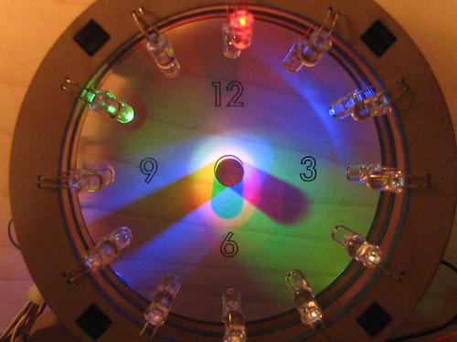
As we have noted, it’s pretty tricky to get good photos of LEDs, but you can kind of get the idea here– just imagine that the colors are bright and vibrant.
In this photo the time is about 6:20:40. (Like many clocks, it’s hard to read with high precision. Even so, the seconds help to create the sense that something is happening.) The short hand, the hour hand, is created by the shadow of the red LED, and points to 6, indicating 6 o’clock. The medium hand, the minutes hand, is created by the shadow of the green LED, and points to 4, indicating 20 minutes past the hour. The seconds hand, the longest one, is created by the shadow of the blue LED, and indicates about 40 seconds past the minute.
What’s *really* neat about this is how the colors interplay. Where all of the LEDs hit, a white color (additive RGB) is produced. Then, as you subtract one of those three colors– as in the shadow of a single LED, the results are subtractive colors, and the hands on our clock face are in the colors cyan, magenta, and yellow. It’s just magical.
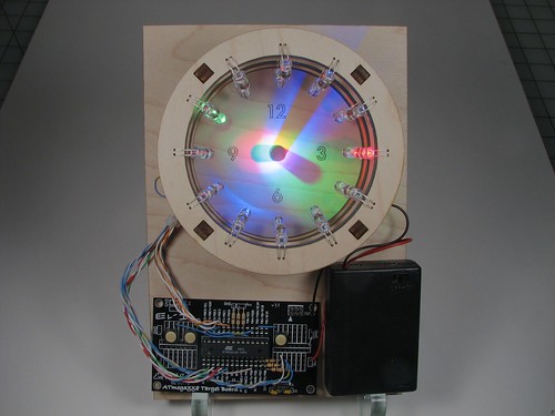
So that’s our new bulbdial clock; you can see additional a few photos in our flickr photo set here.
One more thing: We are thinking about making a kit version of this project (under license from David Friedman)– and we’d really like to have your feedback before we go further. There are a few obvious things that we’ll take care of– like a circuit board with dedicated (and labeled) buttons, a lower-frequency crystal oscillator to reduce power consumption, and holes to hang it on the wall. But we’d like to hear your other suggestions as well. :)
Update (December 2009):
We’ve listened pretty extensively to all of the feedback here (Thanks!) and reworked the project from the ground up. Amongst other changes, the new version has a plug-in power supply and classy outer case. We have just released the kit version, and you can read more about it here.


cover the wood with brushed aluminum. i would definitely buy a kit
A kit FTW!!
Tell here if this Colck is available as a kit, wish it at once :)…..
Really Great thing
Love it. I certainly want a kit so I can put it in my office.
Could you use a frosted front and put the center post on that? Then the LED’s could be inverted to shine up at it and project the arms on the frosted face?
I too like the idea of a sweeping second hand. You could tripple the number of lights on the outermost ring and get a fairly smooth sweep one would think.
Love the idea!
I’m not sure how I’d feel about a kit, but I’d definitely buy one of these if you’d sell it for around $50 or less.
Please notify me when you got a kit – I definitely will buy one (as long as the price is somewhat reasonable)
I would love to build one of these with a kit. I would also want to either utilize an old wall wart or possibly USB power.
Please please please make a kit for this. I’ve been looking for projects working with LEDs and this would be a perfect real world exercise. It can be a tasteful gift for any tech nerd or for anyone to put together and give to non geeks.
Make a mailing list so people can know if/when you might have this completed.
It looks like the minutes and seconds hands are limited to units of 5, which is not very satisfying. I was wondering if lighting two adjacent leds would create a pointy intermediate shadow that would make it more precise. You could modulate the power to have it change shadow shapes gradually for even more information.
Not to be a killjoy, but a clockmotor with 3 leds mounted on the hands would actually do a better job. It would be a challenge to get power to the LEDs but it is doable.
Simple suggestion: put the entire electronics on the outside of a white plastic bowl, where the LED’s project to the inside, keeping the ‘dial’ in the bottom of the bowl. It would require specific focusing of the LED’s, but better visibility of the light throw (nice flat spot), albeit through a diminished angle of view. Electronics are hidden by the plastic, the effect is clear, simple, and hopefully, we can used recycled plastic too! (I’m thinking spaghetti strainer – already has holes!)
i would buy one if you made a kit please!!!
My wife’s a teacher and would absolutely love to build this for her science class. If the kit is feasible in price, she would definitely have a lab in class. As another poster mentioned, this project can be related to many aspect to the education curriculum.
I myself would love build this as well. Feel free to keep me posted!!
mr.flee@gmail.com
PS. Great job. As many mentioned already, a video would be great!!
I’d love a kit, but I wouldn’t want it to be one of those $100 things. If it was reasonably priced, say $20, I’d be down
If a kit were to be offered, I’d definitely buy it.
Count me in, I’d happily buy a kit. And please post a video
I think a kit would be awesome.
KIT! KIT! KIT!
This is beautiful.
This is great, thanks for the inspiration!
I’m trying to replicate it using an arduino and wanted to hear how you’re doing the multiplexing of the LEDs. I set up the loop function to sink the appropriate LED column pin to the right ring pin, but I’m having trouble getting the balance right. If I leave each LED turned on for 10ms then the LEDs all visibly flicker, but if I just cycle between them with no delay then they light really dimly (even adjusting down to a 10ohm resistor). I’d appreciate any pointers you can give.
Thanks!
Please make the kit. I thought about trying to make it from your pics, but I’m not that good. I will also blog about this tomorrow and throw you a linkback, totally.
I for one would be very interested in a kit.
Please please please please please make a kit! And make it an easy kit… specifically with the chip already programmed. I would love to make my own enclosure, but would need the guts! So please please please a kit!
Really cool, nice work. You might consider a solid stack of plywood rings to reduce ambient lighting coming in from the sides.
Justin
I would buy a kit.Else, I think i’d have to much problems on cutting the wood correctly… Really nice project.
Would love to see a kit for a good price once the power usage has been tweaked.
I would see what would happen with a 1 way glass on the front, and cover the sides to darken the interior..
THEn even try reversing the Center Post to the Mirror so that the shadow is displayed ON the 1 way glass..
If you are going to make circuit boards you obviously could make the rings as PCBs… then having 60 LEDs on each ring becomes a possibility, you could put LED dirver(s) on each layer (muxing 180 LEDs would need about 30 pins on the micro or external chips) and the board interconnects could provice both connections and the spacing – might push the price up though… maybe a deluxe model?
Doing ringed circuit boards with 60 LEDs each was the *original* plan; I’m not sure if it’s better to go with that, or with the cheaper and kindof interesting plywood-type construction. It would look great, but the *main* issue is that it’s just a lot of soldering– 180 LEDs –more than really needs to go in a simple kit like this.
—
Windell H. Oskay
drwho(at)evilmadscientist.com
http://www.evilmadscientist.com/
Honestly, I’d lose the seconds before sacrificing accuracy on the minutes…
I agree with the "simpler is better" thought. I also like the "steampunk-edness" of the plywood.
BTW, the moment I saw this article, I pulled out my wallet and paged down to find out where to order :-( Here’s to hoping you make the kit :-)
Change the shape of the post, you will change the shape of the shadow. Make the post pointed, and with some calculations, the shadow, at least one of them will be the same size. An alternate would be really put some design on the post using a lathe so the projected clock hands look like, well, clock hands.
Oh, these are cool. I remember reading that blogpost and thinking about how i could go about making something like it myself. I’d buy a kit if they were avaliable.
Please make the kit! I’d buy one!
oh yeah, Id take a kit great for a fathersday /dads birthday
even if you dont make the kit how about knocking out the parts list for something thats post prototype?
potential customer here. kudos
This kind of circuit is what technologists love! If I could get my hands on a kit I would be sure to build one for a lot of people and recommend it to my fellow technologists. However, I would prefer that the circuitry be hidden and the prodct in its entirety put in some kind of case to make it look more professional. I would want my guests to wonder how it is set up and what it looks like. It is a great idea and sure to be a hit! Please come up with a kit!
I would *adore* a kit for this. I love electronics and it looks fantastic.
I love this clock! I hesitate to ask for a kit, as I’ve never done any electronic work. I wonder how expensive a pre-built clock would be? I LOVE the gaudy factor & would hate to see those colors toned down.
BTW, I get the impression that this clock’s main function is to be cool, while keeping time perfectly, or how it looks from the side being secondary.
Add a top ring, or don’t, but covering it with plastic to protect it from dust IS a good idea.
I would buy one of your kits, that’s the coolest clock I’ve ever seen!
i would deffinetly buy a kid.
If you were to make kits, I would certainly buy one. Within the kit, you really need detailed circuit diagrams and instructions for the average builder. I’d love to make this!
Marks between the numbers, please? Then, kiiiiit! I want to make one of these as a gift. I don’t know for whom yet but oh man do I want to make one. er, well, okay, maybe I might not be too good at making one…any plans on making more and selling them on Etsy or somewhere like that?
I would definitely buy one of these. It would look great with my paper clock that I built out of one of those cut and glue books.
Cool
Sign me up for a kit! And don’t worry about makin’ it pretty – i.e. housing the OCB, etc – that can all be done by the folks assembling the kit. (As well as changing LED colors and such to one’s personal taste.)
Cheers!
I would buy this in a second
Yes, kit’s, kit’s kit’s pls!!!
Please make a kit for this. I’m ordering as soon as it’s up for sale.
You could probably reduce the pin count by tri-stating the pins and using a 6×6 array to drive the LEDs. Maybe you could even use less if you put LEDs back to back, and used a 3×6 or 6×3.
You probably have plenty of pins though. Very cool project.
RGB LEDs? :P
absolutely need it!!!
Oh, I would totally buy a kit for this!
I’m a little confused on how it works. If you have a common-anode connection with the LEDs and you connect the cathodes vertically, wouldn’t that just make one vertical row light up. I don’t get how the other ones light up individually. Anyone shed some light on this for me please, Thanks
I WANT A KIT SO MUCH. ID LOVE TO BUILD AND HAVE ONE OF THESE. MAKE A KIT ASAP. PLEASE