Octolively is an all-new, open source interactive LED surface kit that we’re releasing today. Octolively features high resolution– an independent motion sensor for every LED, stand-alone operation, a variety of response functions, and easy scaling for large grids.
Octolively represents our fourth generation of interactive LED surfaces.
Long-time readers might recall the original Interactive LED Dining Table, the infamous Interactive LED Coffee Tables, or the third-generation, not-very-creatively-named Interactive LED Panels. All of these surfaces were based on fully-analog circuitry with large circuit boards and a fairly high ratio of LEDs to sensors– typically 20:1.
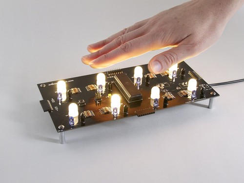
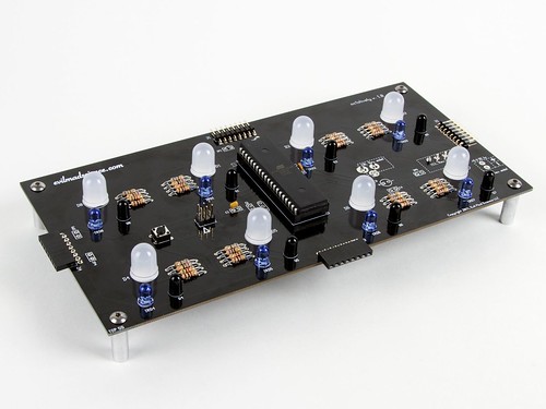 Octolively, by contrast, is based on smaller, lower-cost circuit board modules, “only” 4×8 inches in size. Part of the reason for this is so that there’s more flexibility in making arbitrarily shaped arrays. Arrays can now be as skinny as 4″ wide, or as wide as you like.
Each module features 8 LEDs and 8 independent proximity sensors– one for each and every LED. The LEDs are (huge) 10 mm types, and that chip in the middle of the board is an (also huge) ATmega164 microcontroller.
Octolively, by contrast, is based on smaller, lower-cost circuit board modules, “only” 4×8 inches in size. Part of the reason for this is so that there’s more flexibility in making arbitrarily shaped arrays. Arrays can now be as skinny as 4″ wide, or as wide as you like.
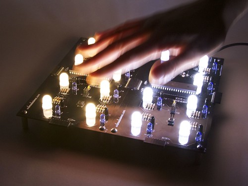
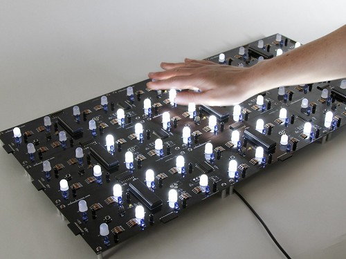
Each module features 8 LEDs and 8 independent proximity sensors– one for each and every LED. The LEDs are (huge) 10 mm types, and that chip in the middle of the board is an (also huge) ATmega164 microcontroller.Each sensor consists of an infrared LED and phototransistor pair, which– together with polling and readout from the microcontroller –acts as reflective motion sensor. The LEDs are spaced on a 2-inch grid, and the edge connectors allow boards to be tiled seamlessly. Because the circuit is now primarily digital, it’s easy to store a variety of response functions in the microcontroller. Our standard firmware contains 8 different response functions– fades, ripples, shadows and sparkles, which you can change with a button press. As it’s an open source project, we’ll expect that (in time), others will become available as well. And, because the entire circuit is self-contained on the module, the surface scales effortlessly– you get very high resolution over huge areas without bandwidth bottlenecks, and no need for a central computer. Of course, static pictures don’t do much justice for interactive LED surfaces. (We’ve embedded our video above. If you can’t see it here, click through to YouTube.) And doesn’t that look good with warm white LEDs? Octolively begins shipping next week. Additional details– including the datasheet and documentation links –are available on the product page.


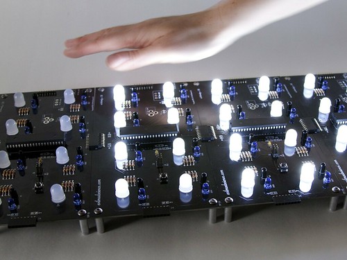
Looks very nice!
One suggestion: you could put the microcontroller, passives, and all other components except the LEDs and sensors on the bottom side of the board. That would give the design more of a sci-fi look.
What’s on the edge connectors besides power? Can pixels on one board talk to their neighbors on the next board to create things like soft edges or waves that propagate across the entire surface?
From the datasheet, pins 4 and 5 on the edge connectors are connected to PB0 and PB1 (T0 and T1) on the chip, which means that they should be able to share communication with each other.
Ya’ll kick so much ass. This rules.
SMT would be nicer, but cool idea.
If we end up making a prefab (non-kit) version of this, we’ll go mostly SMT. But the through-hole LEDs are still much better. :)
Windell H. Oskay
drwho(at)evilmadscientist.com
http://www.evilmadscientist.com/
how about multi colour LED’s?
With RGB LEDs, there would be 24 visible LEDs to control instead of 8, which would increase the cost significantly.
I wonder if a regular LED matrix or an irregular pattern would be more useful — probably it depends on the project.
Therefore, wouldn’t it be a good option to have different soldering positions for the LEDs, the regular one an one (or more) off-positions you can choose from?
With complexity comes cost.
Once you start adding "alternate" locations for LEDs, you have to worry about what happens when some well-meaning customer tries to solder LEDs in EVERY location all at once.
The design for the analog interactive LED panels went through similar discussions. First, some people said that the pattern was "too random", so they made it a little more structured. Then, suddenly, some people said "it’s not random enough".
Of course, since it’s an open-source project, I’m sure people will eventually come up with their own placements for the LEDs in time. It may completely ruin the tile-ability of the boards, though.
Given that the boards were originally designed as part of a ginormous interactive "game of life" display project, the grid pattern was completely appropriate for that application.
Just curious, but how many iterations of the board did you go through to get from the Interactive GoL boards to the Octolively boards? I see some things that look a bit "cleaner" from the original to this version (mounting of the IR pair and resistors, for one), but wasn’t sure if this is more of a version 1.1 (with IGoL being 1.0), or a 2.0, or 2.4, or what.
Glad to see it turned into a product and open source project! :)
There are relatively few changes in terms of hardware. The main difference was the repurposing in terms of design and all new software.
I’ve been wondering for a while now about making an interactive panel/modules like this, for ceiling lighting. I was thinking of using RGB LEDs (like others mentioned above), with IR proximity sensors (module package type). Seeing the table a while ago was nice similarity, and seeing it now in digital, opens the possibilities for ‘other’ uses that I’ve been wondering about.
(Just like other ideas, didn’t get to them…yet)
-bb
Those are HUUUUUUUGE LEDs! Where can you get them?
You can get them at our webstore, right here. :)
Windell H. Oskay
drwho(at)evilmadscientist.com
http://www.evilmadscientist.com/
Is this hardware used in the recent "O Land" videos? http://www.youtube.com/watch?v=V4wHMORwlHY
Those are actually our original Interactive LED Panels, the same ones from the Interactive LED Coffee Table project. :)
Windell H. Oskay
drwho(at)evilmadscientist.com
http://www.evilmadscientist.com/