Don’t you just love nixie tubes? They glow with a lovely neon color and have gorgeous stylized numbers– something you can’t get with a dot matrix– or even sixteen-segment LED or LCD display.
Recently, we disassembled a well-loved tube when there was a photogamer challenge to break something, and so we had a chance to peek inside and look at how they are made.
Warning: This article contains graphic images of the dissection of vintage electronics which may be disturbing to some viewers. (No working nixies were destroyed in the making of this article.)
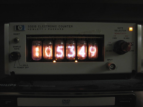
From the 1950’s until about 1970, nixies were a dominant display technology. “NIXIE” is actually a brand name for display tubes made by Burroughs, and the proper generic name might be “cold cathode neon readout tube.” However, as with facial tissue, a single short word involving the letter ‘X’ had more widespread appeal. Whatever you call it, they were used in all manner of electronic instruments that needed to display numerical data until they were ultimately made obsolete by the introduction of LEDs. One of the common places that you can find nixie tubes is in old scientific instruments, like this old HP 5321B frequency counter which has been converted into a clock. (It’s 10:53:49 PM.)
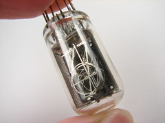
The tube that we’re taking apart is the kind found in the clock (counter) shown above. It’s a medium-size, upside-down vertical, side view, medium digit nixie tube with a neat rounded bottom– or top, depending on how you look at it. The HP part number is 1970-0025, equivalent to Burroughs B-5560 and National NL-918. You can get tubes of this type from Sphere for $10 each.
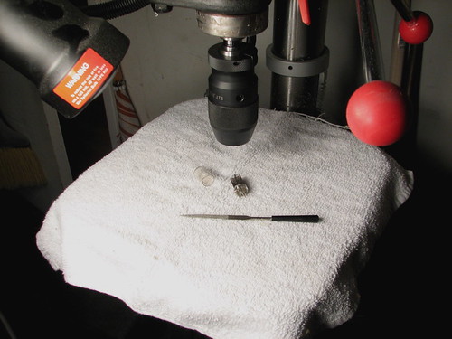
The ideal tool for getting at the insides of the tube would be a lathe. We didn’t have one handy and so we had to improvise. The tube turned out to fit into the keyless chuck of our drill press, so we directly (and gently) clamped it in the chuck. With the drill press set to its lowest speed, 300 RPM, we held a fine-edged diamond file against the base of the glass tube.
This worked very well. After a couple of minutes, the scoring from the file turned into a neat cut, and the top of the tube fell right out onto the rag we placed strategically on the platform.
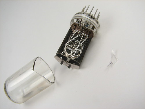
It was a fairly clean break, but the top of the tube cracked in the drill chuck, probably after the tube bottom was removed.
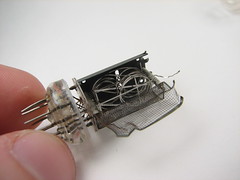
Next, the mica insulator at the top of the tube (bottom of the digits) was removed. The screen around the tube was held on by several tack welds. You can start to see the individual numbers here, from the side.
The individual numbers are held apart by ceramic spacer beads. Notice that there is an extra eight, but upside down. It is the one with the wire sticking out. That one was used as a wire, and did not light up.
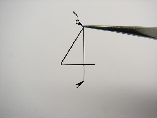
Here is the real reason for taking apart the tube: the beautiful numbers. The four is out in front, which makes it seem brighter. When in use, you can tell what number is lit by placement almost as much as by shape.
Each of the numbers is connected through a ribbon-shaped wire to a pin on the base. Fortunately, these can be cut with fine-point scissors.
Just a few more pieces to go. With the metal screens removed, you can see the remaining characters much more clearly.
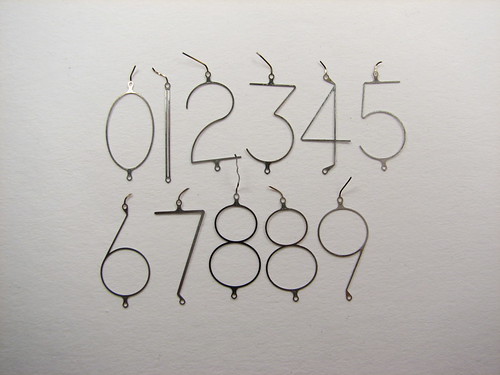
The set of numbers is beautiful. Notice that there are two identical 8’s, and that the “one” is made of two lines. This helped to keep it as bright as the other numbers in spite of being so much smaller.
We hope you’ve enjoyed this as much as we did. We’re already plotting what to take apart next…




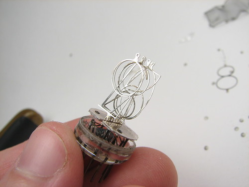
The upside -down eight in the middle of the stack of digits is wired to the anode screen that was removed at the beginning of the autopsy. The extent to which the neon around any given number will ionize (and the potential at which discharge can occur) depends partly on the distance between the anode and cathode. The eight in the middle gives a sort of maximum-distance guarantee for any given numeral, without which specifying a single firing voltage for all cathodes would be difficult — in other words, without that eight, digits near the back of the stack (like one) would require significantly more voltage to light up.
Eight was chosen in most cases because its presence would be less noticable than that of a second anode screen, and its surface area is the largest compared to other numerals.
Another breed of nixie tubes with fewer pins – called “biquinary” nixies – has a screen near the location of our inverted eight, and for precisely the opposite reason: to isolate one set of digits from the other. I’ll leave you to work that one out on your own. :)
Thanks– that’s great info! I hadn’t thought of distance as being the reason for the "middle" eight digit, but it makes perfect sense now that you mention it.
It’s also certainly true that it’s hard to see that digit in the middle– you’d never see it unless you were looking for it.
—
Windell H. Oskay
drwho(at)evilmadscientist.com
http://www.evilmadscientist.com/
You know that these tubes contain Mercury? You need to be quite careful doing this – the digits are typically nickle or a compound thereof, but to help reduce sputtering and to increase tube life a small amount of Hg was added – tubes that have this have a "purple haze" round the digits when illuminated.
Just be careful what you do with old tubes…
Nicko
Yes indeed- these are the “long life” tubes and if you look closely at the photo of the glowing tubes, you can see the purple color as compared to the (plain) neon bulb decimal point.
Yup– look at the pretty pictures and don’t do this at home unless you want to breathe extra mercury!
—
Windell H. Oskay
drwho(at)evilmadscientist.com
http://www.evilmadscientist.com/
I’m thinking you could make a nice set of earrings (or five and a half sets) from these. Too bad you let all the "glow" out though.
Unfortunately, these tubes contained mercury, so using the parts for earrings is not such a good idea.
Aside from the mercury, they’re still really fragile. It might be better to make new, thicker, versions using the same font and design, but etched out of some clean metal.
—
Windell H. Oskay
drwho(at)evilmadscientist.com
http://www.evilmadscientist.com/
Well, they could be encased in clear acrylic resin maybe.
Bah, this post started me on a four hour surf-a-thon to learn about nixies and now I find my evening is completely shot and my wallet is lighter. Thanks. All I wanted to do was to check out the mad geniuses behind the LED table. Sheesh!
Thanks for taking the tube apart and exposing the number shapes. Just the inspiration I needed to build my virtual Nixie clock
http://www.chumby.com/guide/widget/Another%20Nixie%20Clock
What are the order of the digits from front to back? I suppose the order was carefully chosen based on some reason. Would like to know that.
It’s been a while, but I remember that they seem to advance back to front, then front to back, with 4 at the front. Seems that they try to stagger the digits.
Windell H. Oskay
drwho(at)evilmadscientist.com
http://www.evilmadscientist.com/
Three questions came to mind when I read this (back-round on myself, I am a mechanical engineer, so speak slowly, simply and enunciate with the electrical jargon). I have a specific project in mind.
1) What sort of signal/power do these things need to operate?
2) What sort of lifetime do they have?
3) How do they handle vibrations?
Vibration: pretty good, but they’re made of glass.
Lifetime: Pretty good; these haven’t been made since the 70’s for the most part, and many of them still work today.
Driving them: Lots of information on the net, no need to duplicate it.
Start here, for example: http://www.glowbug.nl/neon/HowToDriveNixies.html
Windell H. Oskay
drwho(at)evilmadscientist.com
http://www.evilmadscientist.com/
Thanks for the time travelling, the 50s style is really lovely !
What voltage do these take? approximately 170v (at 1 to 3 mA)
What life do they have? Some (non mercury types) are as low as 5000 hours, many are in excess of 200,000 hours (over 20 years CONTINUOUS use) – mine have been running for 8 years (24/7) with no sign of darkening and they weren’t new when I had them. If you put too much current through them then the lifetime will be shortened.
Vibration? – don’t! people have put them on motorbikes and they don’t last.
Cheers, Andrew.
(member of neonixie-l google group – we play with these tubes!)
From the "Ceramic Spacers" photo, they appear to be, front to back:
4, 5, 6, 7, 3,
upside-down 8,
8, 2, 9, 0, 1
As to why they’re in that order, I have no idea, they just are. It may have something to do with resistance and voltage needs, as koolatron hinted at, or pin arrangements, or something else entirely.