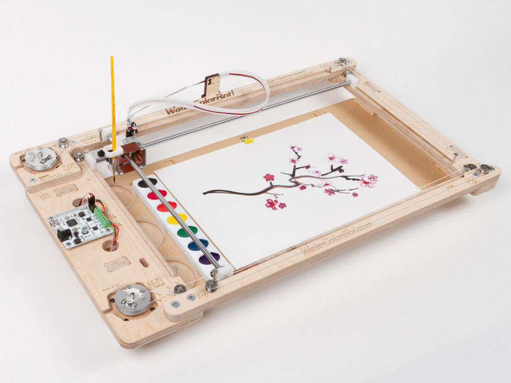
We are very pleased to introduce something that we’ve been working on for most of this year: WaterColorBot version 2.0!
The WaterColorBot is our collaboration with Super Awesome Sylvia: A friendly art robot that moves a paint brush to paint your digital artwork onto paper, using a set of watercolor paints.
Version 2.0 brings it to the next level with some greatly improved hardware. First and foremost, the carriage that holds the brush has been completely redesigned:
The carriage on the original WaterColorBot was made from laser-cut plywood, with nylon bushings and two simple delrin strips that formed the vertical flexure translation stage. (You can read more about the original carriage here and here.)
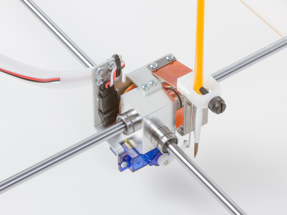
The new carriage consists mainly of two pieces of metal. The center block of anodized aluminum is CNC milled, and houses crossed linear roller bearings. Wrapped around that is a laser-cut and formed aluminum part that mounts the brush-lift motor, cable guide, and the flexure stage.
The new flexure stage is built with two custom flex circuit boards, used in this case as mechanical flexures. Each board consists of a very thin (0.1 mm, 4 mil) Kapton sheet with a thin fiberglass (G10/FR4) stiffener on its center section. With the two ends of each sheet clamped rigidly and the stiffener in the center, each flex circuit is to flex only along two well-defined lines. And with two boards, it forms a neat parallelogram linkage, without the slop that one might encounter in multi-part hinges. The net effect is that this new flexure stage has remarkable stiffness compared to the old design.
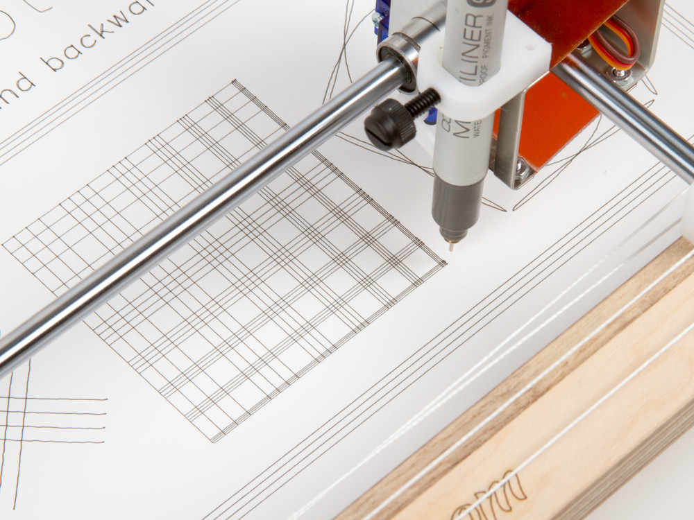
That stiffness, combined with the improved performance of the linear ball bearings makes this a more precise WaterColorBot. Not that you could even detect the improvement with a fat brush and watercolor paints, but things are looking quite good even with using ultra-fine point drawing pens, as you can see above.
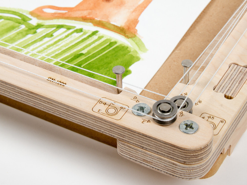
The second major change is to the system of Spectra cords that the stepper motors control in order to move the carriage. Previously, the cords were guided around 11 plain bearings (stainless steel solid rivets) and 3 ball bearings. We’ve simplified this into an arrangement of just 8 ball bearings— four for each motor. The ball bearing pulleys have also been updated to use wide V-groove bearings that are easy to wrap the cords around.
Which brings us to the third (and last) major change. Thus far, WaterColorBot kits have shipped “some assembly required” — with all the major components built, but the cord lacing left to the end user. As of 2.0, WaterColorBot kits now come fully assembled and tested. That doesn’t make them any less hackable, but it does mean that you can get up and running faster.
Version 2.0 includes the same CNC machined aluminum winches that we introduced back in August. Tiny detail: we’ve carved a subtle indentation into the wood around the winch that makes them a little easier to turn by hand.
The new WaterColorBot kits will begin to ship right after Thanksgiving. And a bonus present for the holiday season: Version 2.0 is priced the same as the previous version, it’s just a whole lot more awesome per dollar.


Congrats! Cool, flex circuit boards!!!!! It is mentioned that they are used for the mechanical flexures, was that the only purpose in mind?
Eventually will there be traces on them to add electronics directly to the end effector? Maybe like an LED, or a motor so that the tip of a paint brush is constantly spinning in a circle.
Also why did the flex boards have to be custom if they are just rectangles with holes in them? And how did you stick the fibreglass to the board? Just super curious about these! It looks really spiffy.
Thanks!
These were purpose-designed as mechanical flexures only; we haven’t really thought about using them as electrical connections. If we did want to use them that way, the hardest part would be figuring out how to make electrical connections to them while also clamping them rigidly enough to work well as mechanical hinges.
These are circuit boards, made in a traditional flex circuit board manufacturing process. The gerber file specifies the shape of the kapton base layer (a rectangle with holes), and the shape and location of the stiffener (a rectangle without holes). Usually, a stiffener like that is applied with an acrylic-based adhesive. Using the established process lets us get a thing like this made and assembled for us in a cost-effective manner, by companies that do this all the time. If we didn’t do it this way, it would be a matter of creating custom stampings, and a custom assembly process.
That is very cool to see them used like this. How many other materials did you try before flex circuit boards?!
Maybe one washer on each of the screws between the board and metal could make just enough space for some small wires poking out, while still clamping rigidly.
(It doesn’t really matter anyway since for the example purpose, one could just string the cables from the end effector to the nice new gantry. XD)
Neat to hear about these. Thanks for answering my questions!
We’ve tried quite a few other materials, but the thing about the flex PCB is that it comes as an assembled unit with the integrated stiffener. We’ve been working towards using that for so long that it’s almost hard to remember the other approaches that we considered.
We tried using a delrin strip (as previously) with laser-cut perforations or cutouts, to preferentially weaken it at the hinge points. Another material that could work well is polypropylene, which can be injection molded or stamped to have a “living hinge” — a thin section that flexes while other thicker parts do not.
Any way we can order an upgrade package? Our original bot never worked for us because of the bearings and issues with the carriage sticking. We’d like to give it a second chance.
Yes, we do have an upgrade kit in the works. The “upgrade” carriage has an extended brush holder, that is adapted to hold the brush in the same place that your original carriage did. Please contact us directly by e-mail (or through the contact form) for more information.
And, even if you don’t want to do that, we can probably help you get up and running with your current setup. Most problems that people get stuck on turn out to be pretty easy to resolve, but the solutions can be counterintuitive. Again, please contact us directly for tech support.
Have you given any consideration, as a future expansion, to use a laser engraver ‘head’ instead or a brush or pen?
We have certainly talked about it, and there are some people (e.g., here: http://www.evilmadscientist.com/2014/watercolorbot-laser/ ) working on adding a laser. It would work quite well, but safety and liability concerns are paramount. Lasers are great, but they do damage eyes far more easily and permanently than anyone (in our community, at least) seems to acknowledge.