All posts by Windell Oskay

About Windell Oskay

Co-founder of Evil Mad Scientist Laboratories.

AVR programming trick: Sharing target boards

2313-25 (plain socket)

This week, Brad wrote in with an interesting question: Can you program the ATtiny25 on one of our ‘tiny2313 target boards? And the answer is yes: you can, with just a trivial modification.

Okay, back up– a little context here. The ATtiny25 and the ATtiny2313 are examples of AVR microcontrollers, the little brains that power many of our projects.
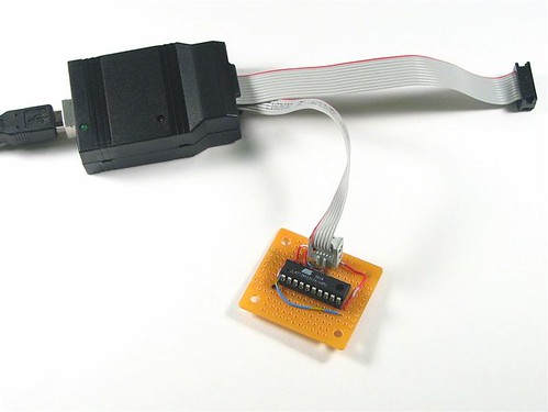
To program these chips, we use a usbtinyisp programmer, hooked up to a minimalist target board.

USBtinyISP & simple target

The target board basically provides a programming header that’s hooked up to the right pins of the chip, plus some way to power the chip– often through the programmer itself.

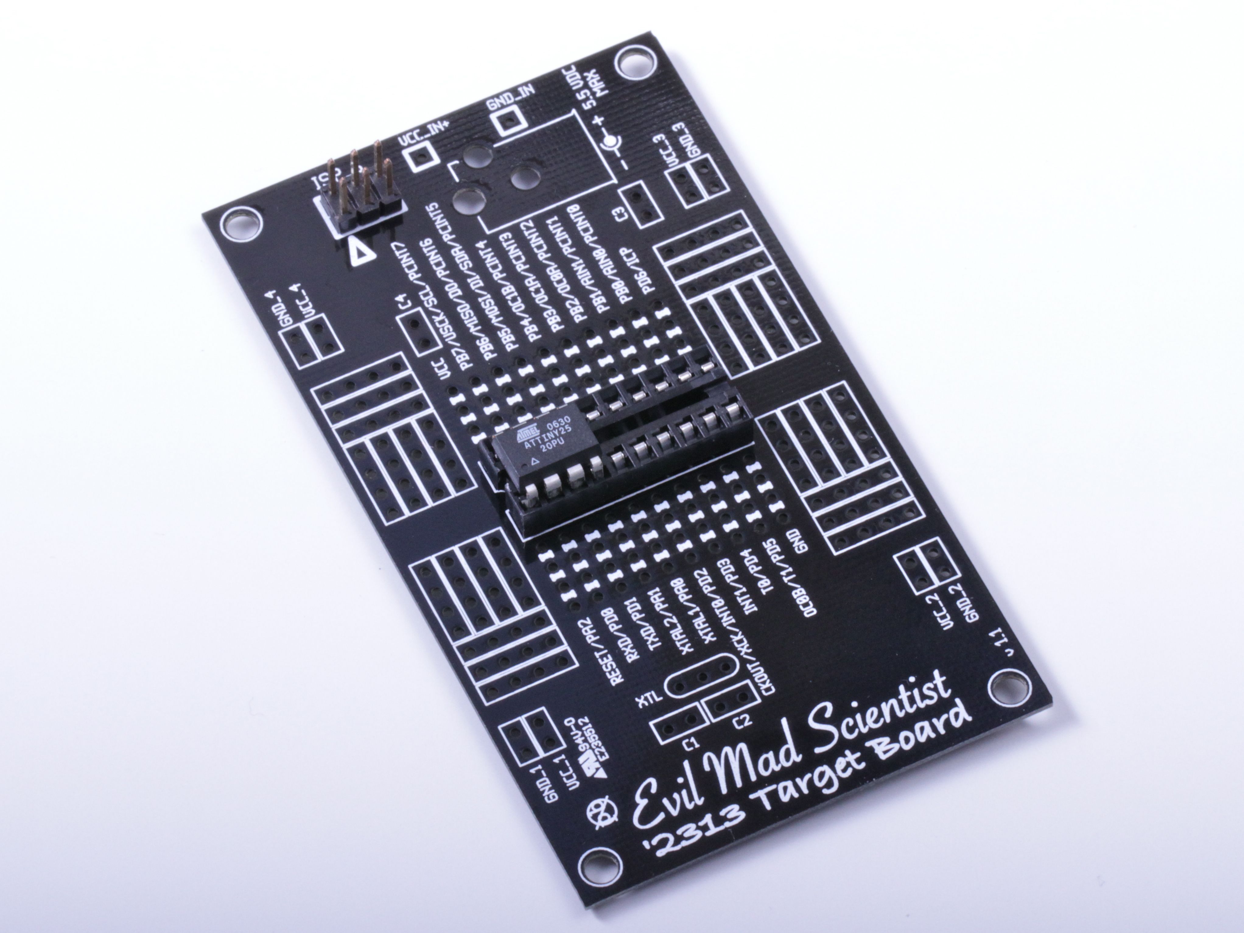
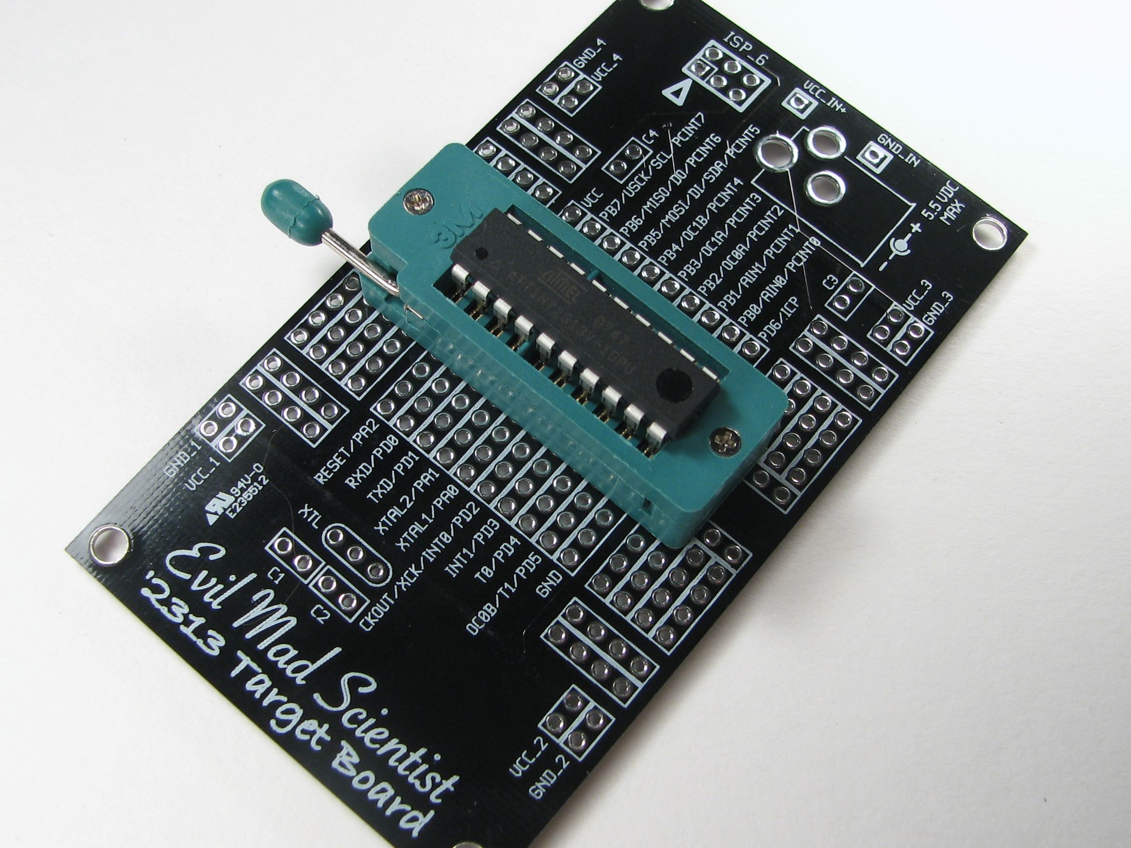
After hand-wiring up one too many minimalist ‘2313 boards like that, we also made a printed circuit board version of the ‘2313 target board. Normally, it looks something like this, with an ATtiny2313 in a ZIF socket:
2313Card - 4

But, back to the question. The ATtiny25, ATtiny45, and ATtiny85 are a family of 8-pin AVR microcontrollers that are not pin compatible with the ‘2313. However, at only 8 pins instead of 20 pins, they’ll definitely fit in the socket… somewhere.

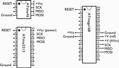
Looking at the datasheets and pinouts for the the ’45, ‘2313 (and the ‘168 that we also have a target board for), we can identify the lines used for programming: MISO, MOSI, SCK, and RESET:


The chips also need power and ground connections to be programmed, of course. Now if you notice, the connections for the ‘2313 and ’45 are very similar– in fact, almost identical if you line the chip up so that pin 1 goes where pin 1 of the ‘2313 normally would. The one remaining difference is that there’s no ground connection to pin 4 of the ‘2313.

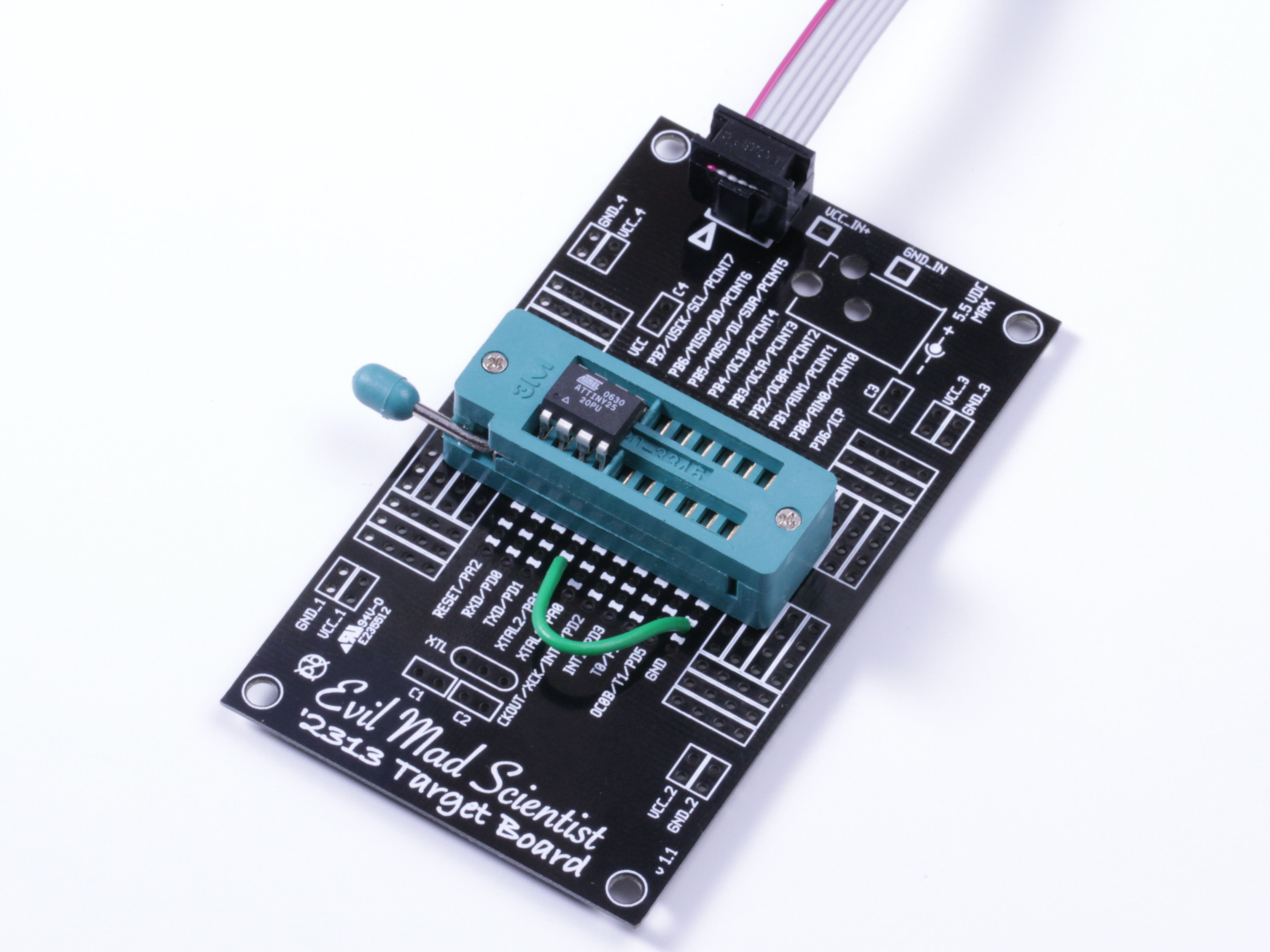
2313-25 (fixed up)

So, adding a wire from ground– pin 10 of the ‘2313 –to pin 4 of the smaller chip (an ATtiny25 in our photo), and lining up pin 1 to pin 1, we’re ready to go. And yes, it works like a charm.
If you do use this method, there are a few (possibly obvious) things worth noting:


  • You need to be careful to line up pin 1 of the chip to pin 1 of the socket.
  • Be careful if or when you put a ‘2313 chip back in the socket. It will draw a lot of current if you set pin 4’s to a high output level– it’s shorted to ground. (Better: If you want to go back and forth, use a switch, not a wire.)
  • Keep in mind that the pin labels on the target board are for the ‘2313, not the ’85.

Going one step further, you could also potentially program the ’25/’45/’85 from the ‘168 target board: it only takes a couple more wires. To do so, line up pin 1 of the ’25 to pin 9 of the ‘168. Add two wires this time, from board-reset to chip-reset, and from board-ground to chip-ground. You’ll also need to connect AVCC (analog power supply) to VCC. A little more work, yes, but still a good hack.

A funny batch of LEDs

10 mm LEDs

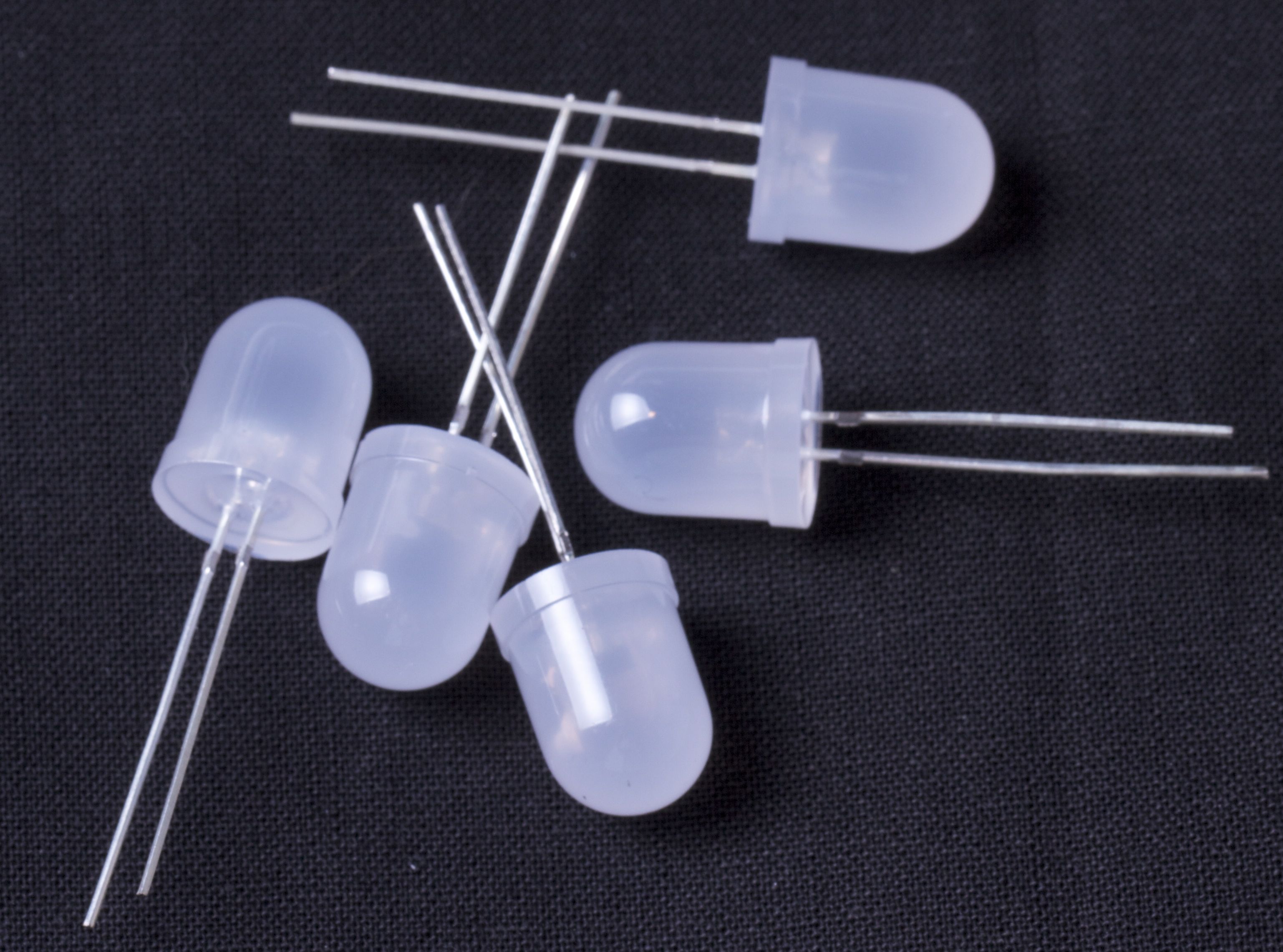
A few weeks ago we got a batch of LEDs– a sample order from a new vendor. These are 10 mm diffused white LEDs, much like the ones that we use on the Peggy 2 or in the LED Ghosties.

On the surface, they look okay. But after lighting them up, we noticed something funny in a few of them that led us to discover their deep dark– or really, shallow and clear –secret. Continue reading A funny batch of LEDs

The 2010 Open Hardware Summit

Picture 9

We are helping to sponsor the 2010 Open Hardware Summit, which is happening next month, Thursday September 23, at the New York Hall of Science. That’s two days before, and at the same location as, Maker Faire NY.

The summit agenda has just been posted: it’s a full day of talks and discussions about open source hardware, its meaning and its implications. I’ll be part of the panel discussing open hardware licenses and norms which will also be taking questions online– so you can participate even if you can’t make it to the event.

Tickets for the event are on sale now and include a 1-day pass to Maker Faire. We’ll hope to see you there!

Linkdump: August 2010

Electronics Flea Market, 8/2010

Fleamarket_2010_08_14 - 08

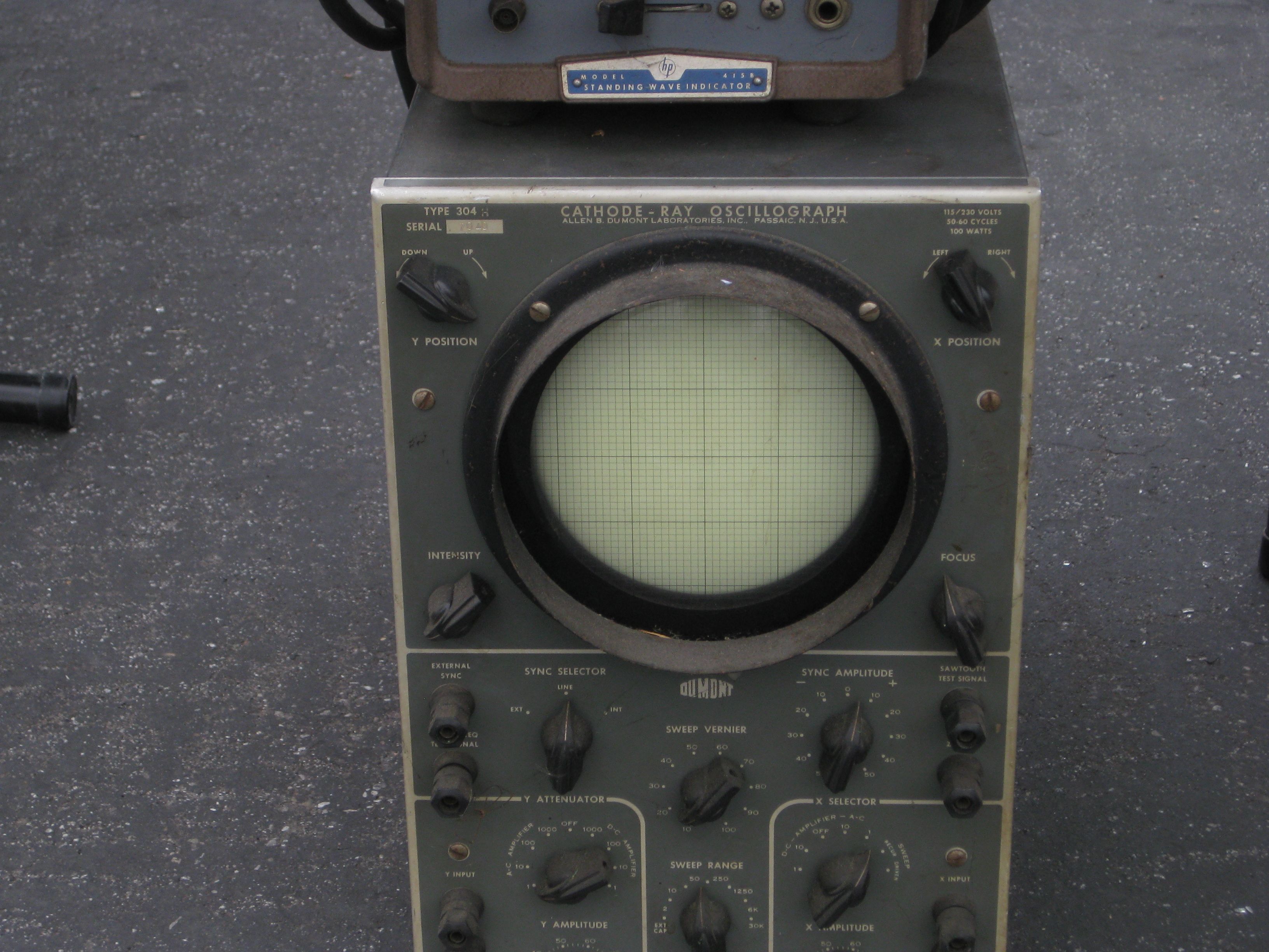
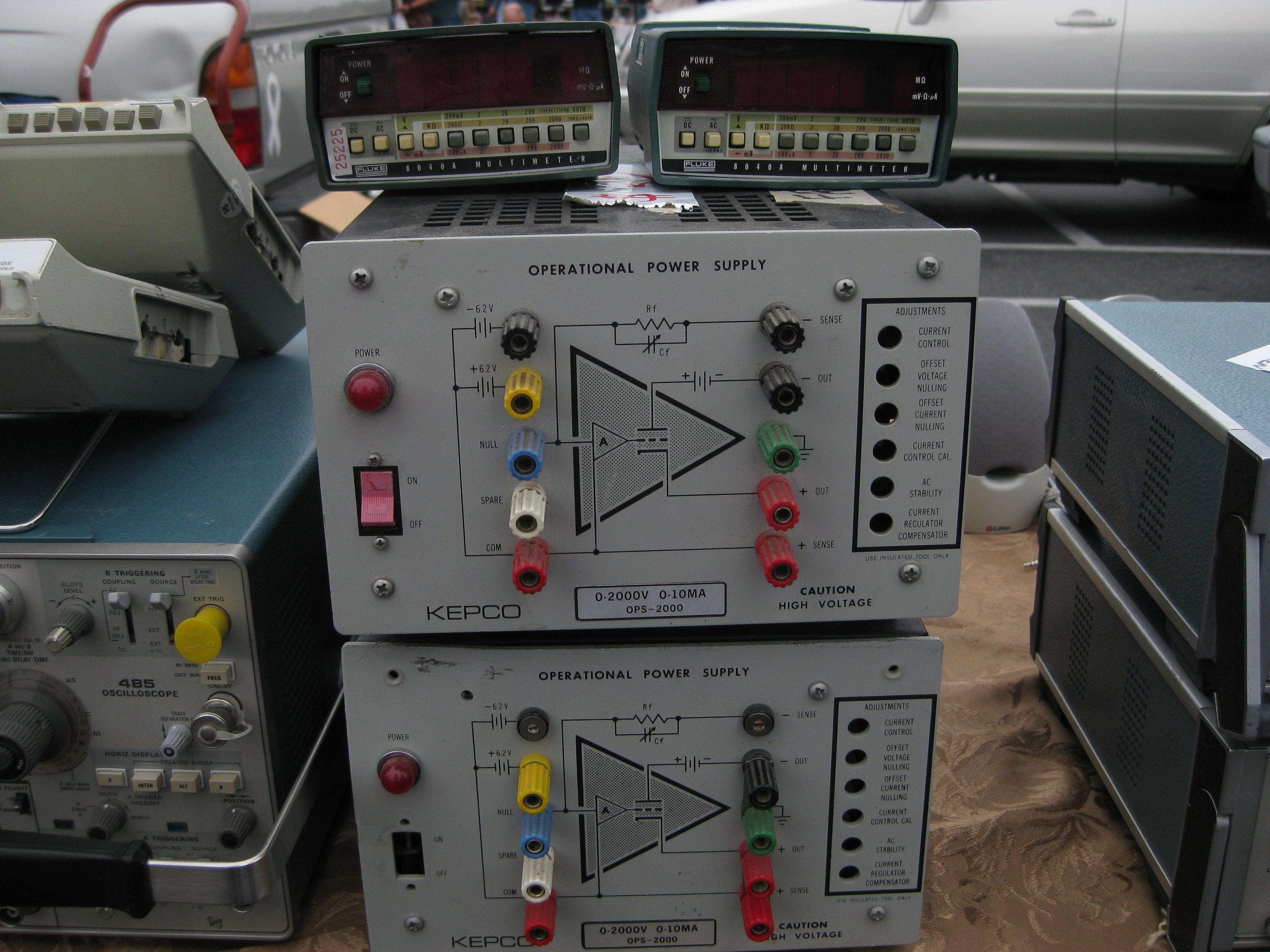
We’ve just posted a few pictures from last weekend’s fantastic Electronics Flea Market at De Anza College in Cupertino.

Fleamarket_2010_08_14 - 15

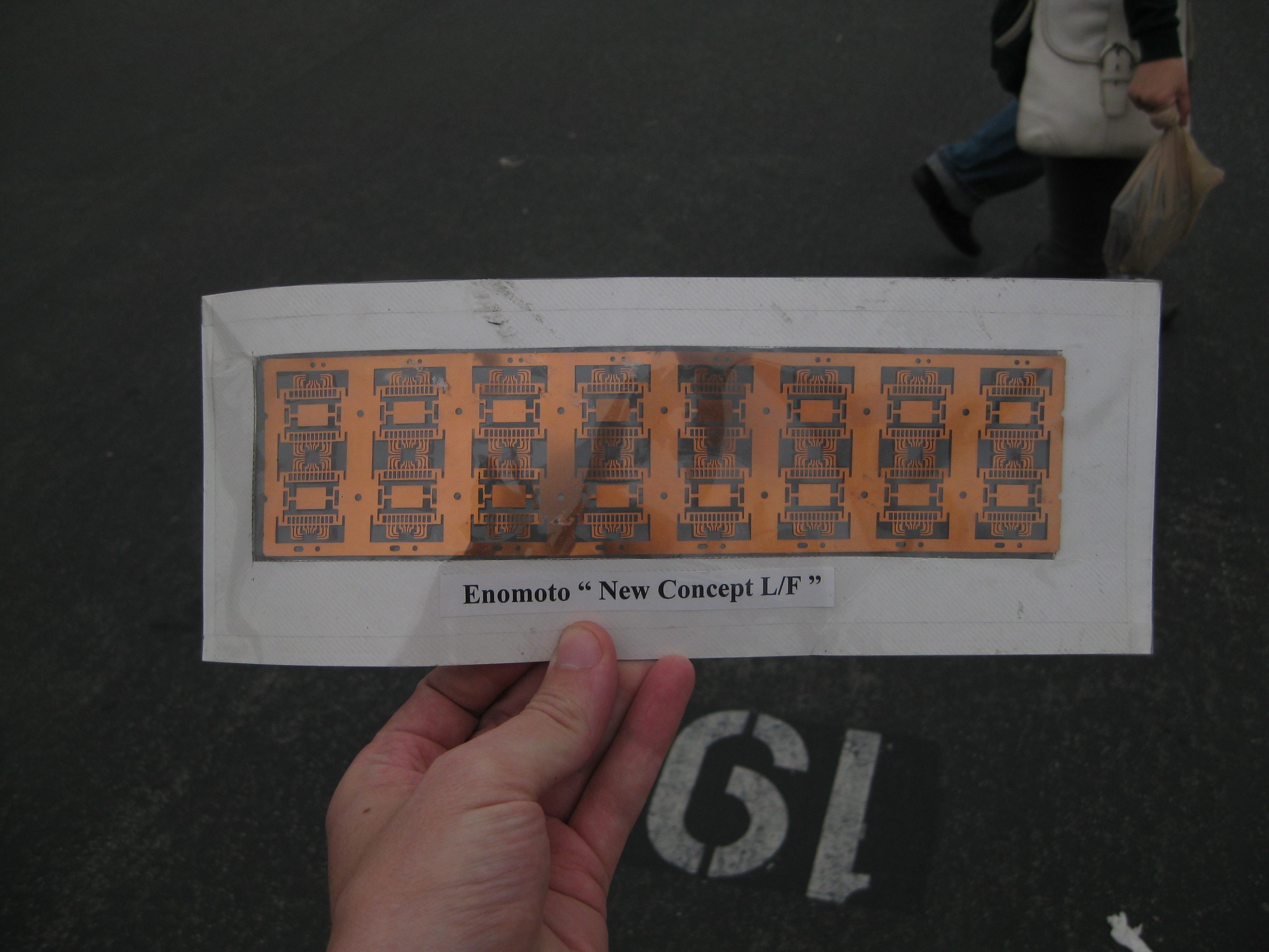
One interesting thing that we came across: a set of leadframes not so different from those that might be made from that photomask that we wrote about a couple of weeks ago.

Fleamarket_2010_08_14 - 01

Only one two more flea markets left this year, September 11 is the next one; mark your calendars and we’ll hope to see you there!

(For a few more, check out photos from another electronics flea market a couple of years ago here.)

Corrected 8/16/10: two more flea markets left for 2010– Sept. 11 and Oct. 9.

On the design of the Bulbdial Clock

bulbdial-details - 12

bulbdial-details - 20

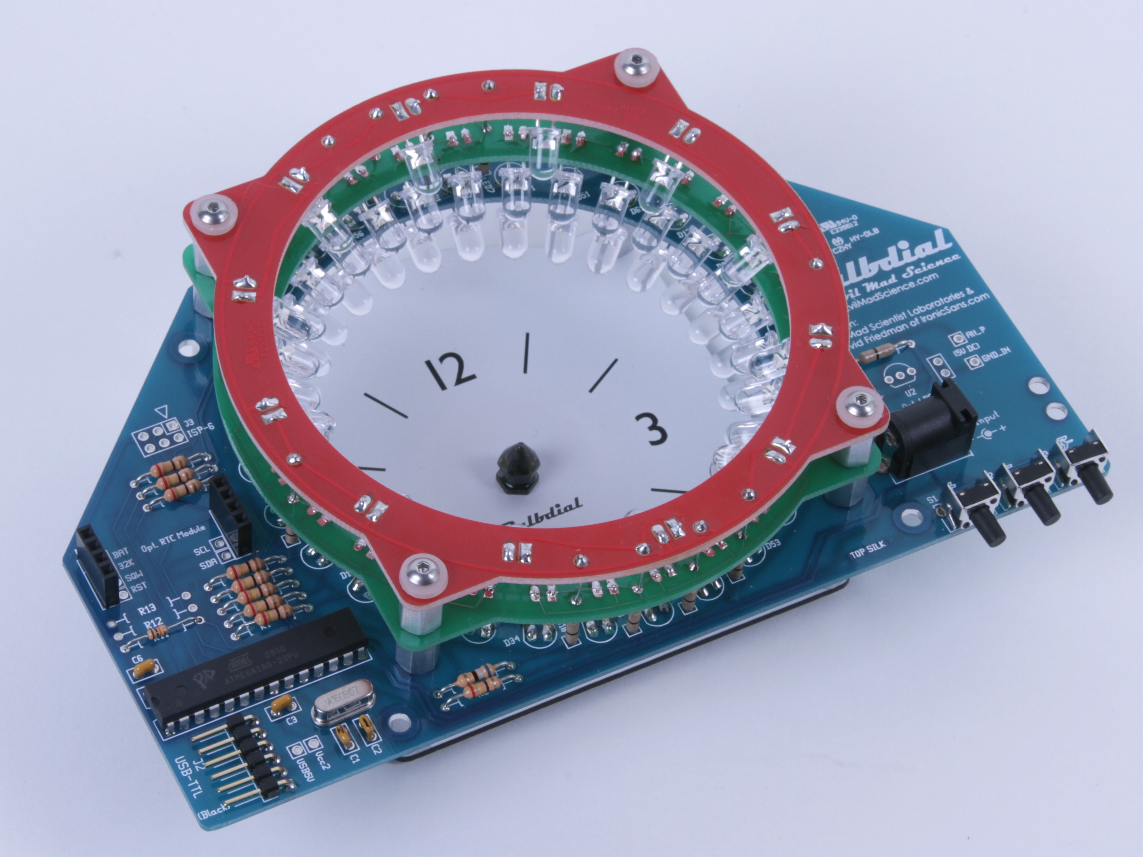
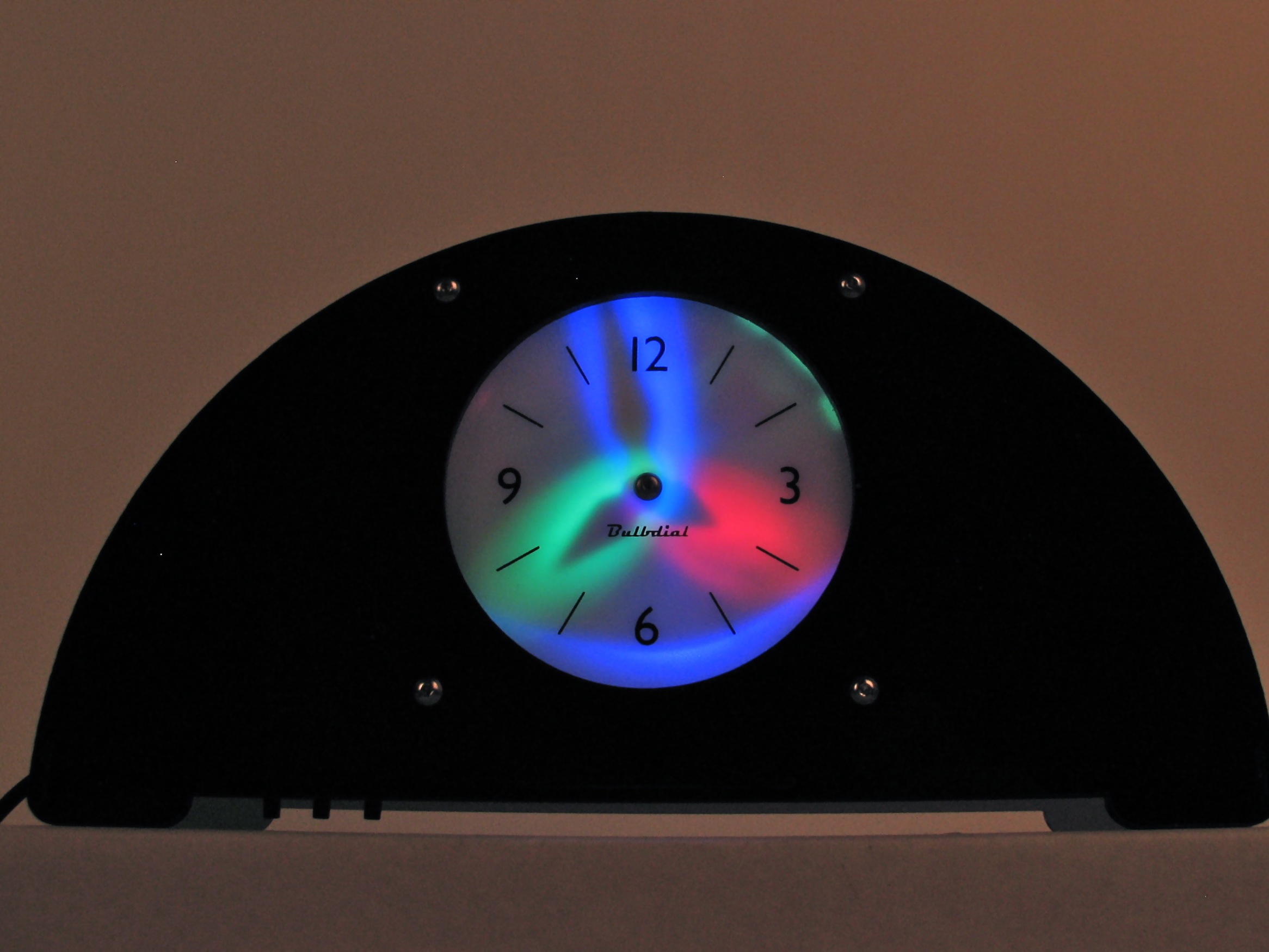
One of our favorite projects of the last year is our Bulbdial Clock, an LED shadow clock based on an idea from Ironic Sans. And, while we have written a fair bit about it, we haven’t yet taken the time to describe some of the interesting technical details.
So in what follows here, we discuss some of those details, with an emphasis on a few in particular that we’ve been asked about. First, the process of designing and prototyping “funny shaped” circuit boards, but also charlieplexing LEDs in a mixed array, and (finally) getting that rear-projection scheme to work.
Continue reading On the design of the Bulbdial Clock

More cool electronics tools

Cable tie tool 1

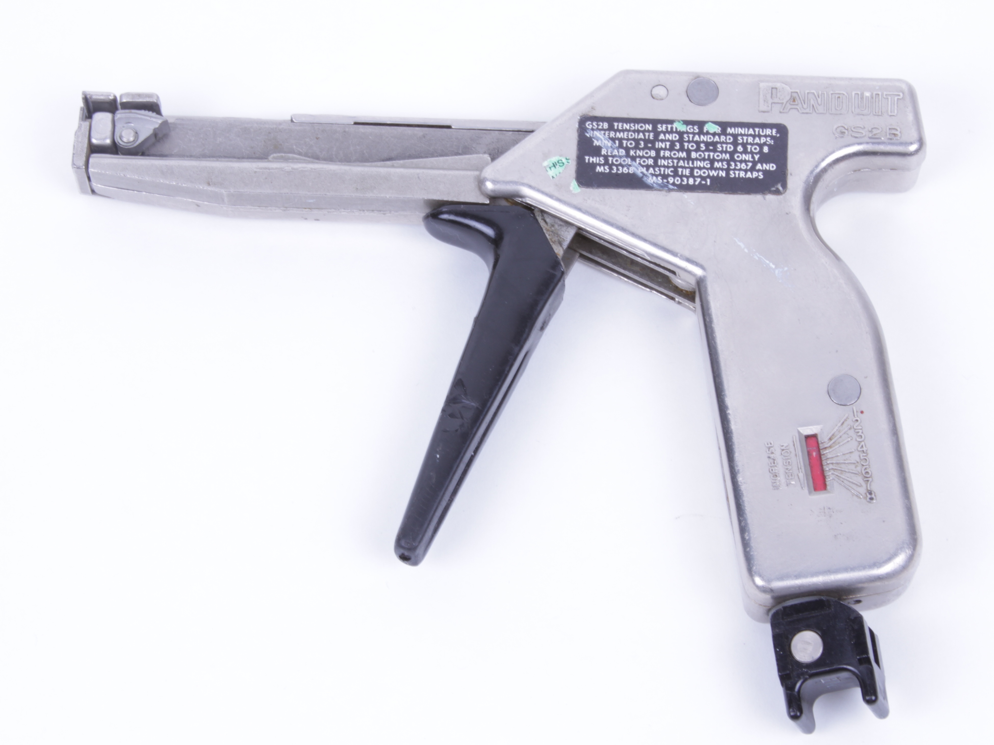
What is it? Hint: your life depends on tools like these.

Some time ago we wrote about five relatively obscuretools for doing electronics. But, five tools barely scratches the surface of the stuff out there, and here are a few more of our favorites. In this roundup we’ve collected some handy–and even important –tools along that you might not have seen before, along with some best-of-breed versions of everyday electronics tools.

Continue reading More cool electronics tools

Advancing open hardware with a few clear words.

2313Card - 2

Over the last few years we’ve been excited to be part of the rapidly growing open-source hardware community. One of the recurring issues in this community has been the lack of agreement on what constitutes an acceptable license for open hardware. For open source software, there’s a common language to start with: the Open Source Definition. But where is the analogous root document for us hardware folks?


Of course, there simply isn’t one. Or rather, there hasn’t been one until now.


Over the last few months, we’ve been helping to hammer out a draft definition of what it means to be open source hardware, in collaboration with open source stars including folks from Chumby, Bug Labs, Sparkfun, Arduino, Adafruit, MakerBot, Eyebeam, Make, and Creative Commons, amongst others. It’s a modest but important step in defining what it means for a project to be open hardware.

The current draft definition is labeled version 0.3, and hopefully we’ll be advancing it towards a 1.0 in the coming months. There’s an Open Hardware Summit scheduled to take place before Maker Faire NY. As things advance we’ll be working on ways to connect to actual licenses and to the other needs of our community. If you have the inclination, please check out the draft and see what we’ve been up to.

Evil Mad Science in Sacramento, Santa Clara and Detroit

Eggbot

Yes, we’re venturing out of the lab:


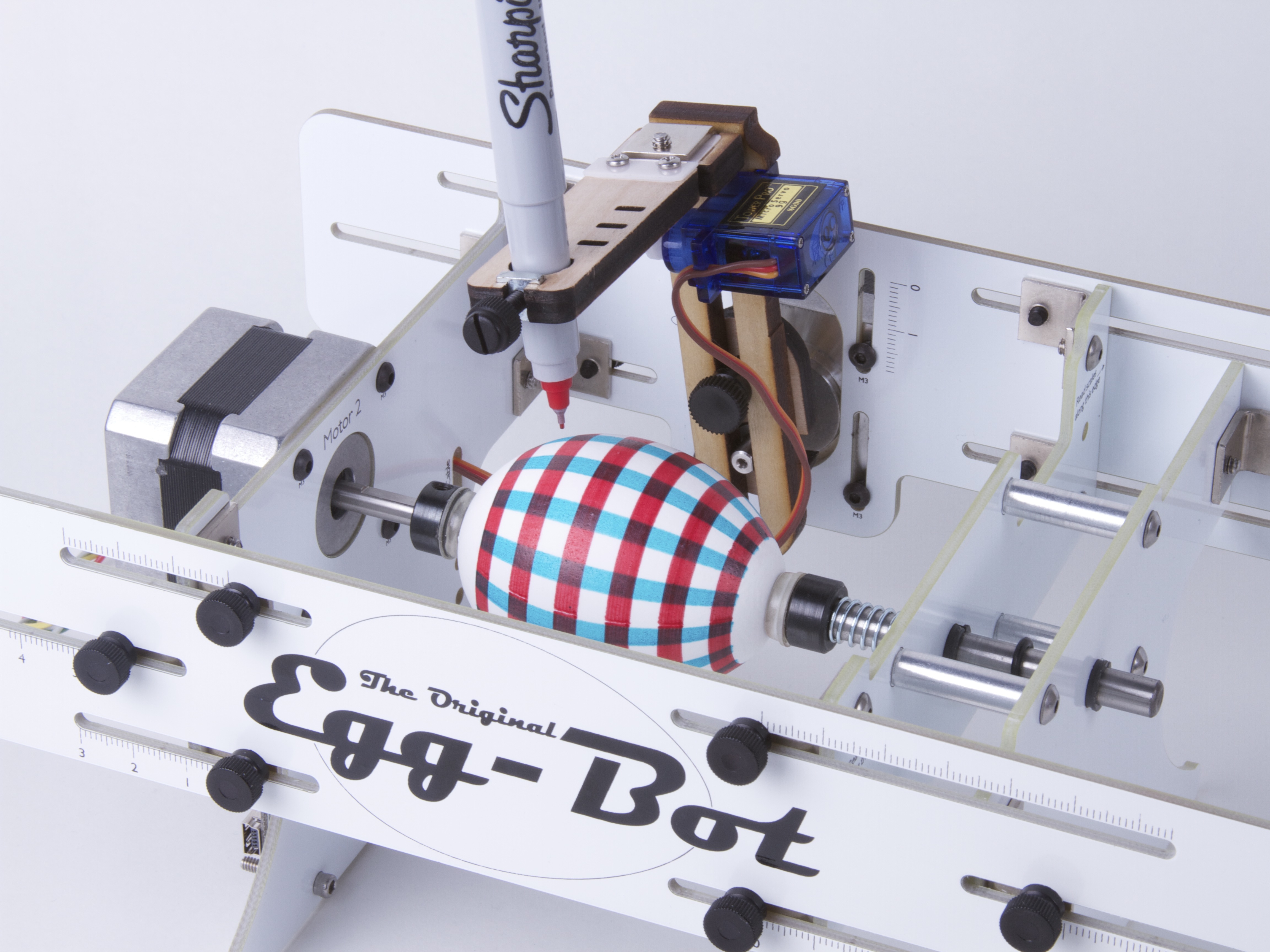
Saturday, July 17, we’ll be demonstrating Egg-Bot at the California State Fair in Sacramento. We’ll be in the Industrial & Technology Education building.


Sunday, July 18, we’ll be taking Tabletop Pong (and maybe Tennis for Two) to California Extreme in Santa Clara, CA. California Extreme is an event with a terribly vague name that is probably your only chance to play Gauntlet, Orbiter-1, and Hyperball on free-play!


July 31-August 1, we’ll be in Detroit, MI at Maker Faire with Bruce Shapiro and Egg-Bot.


We hope to see you there!

EggBot photo from San Mateo Maker Faire 2010 by madichan (licensed under cc by-nc).