Neat-o: our site was picked as one of PC Magazine’s 100 Favorite Blogs!
All posts by Windell Oskay
October Linkdump
- After my video has had 10^6 views on YouTube, I have learned, firsthand, the sad truth about such things.
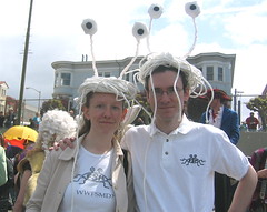
- Costume for people who like Big meatballs.
- The ID Please flickr group.
- Cute 500 watt cat
- My new favorite expression: “Sneakier than a dehydrated grape brick.”
- Whoever put together the graphs on page 9 of this PDF datasheet (for an SMT DC-DC converter) should be shot.
- Hey Okies, what’s with your tasteless new license plates? (via).
- I bet that magnetically controllable liquid photonic crystals would be fun to play with.
- I could look at this table of data structures all day long. link.
- I bet that the people who run this blog are as freaked out by looking at Evil Mad Scientist as we are when we look at their page.
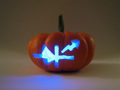
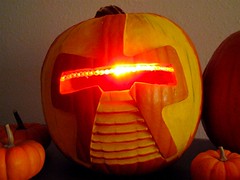
- I like LED Jack o’lanterns
- List of electrical plugs in different countries. Yup, that’s useful.
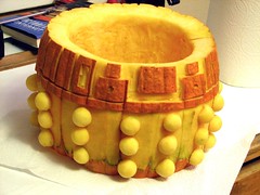
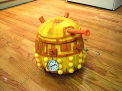
- I like that the BBC has an updated Dalek Cake recipe.
- Beware, there may be Daleks already lurking in your kitchen.
- I wish that I had a good excuse to build a web site based on tiddlywiki; I really like the interface.
- Speaking of awesome things, check out this video made with Google Street View. It should be longer.
Time to Make a Cylon?
Yay! We finally got our copy of the Make: Halloween Edition.
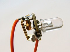
This special issue is actually available in two different covers, but we particularly like thisversion because of that little starburst: “Make an LED Jack-O’-Lantern!”
On page 60, you can find the article that we wrote about how to build the Larson Scanner (named after Glen A. Larson); a scanning eye for your old-school Cylon or KITT pumpkin projects.
The article is actually a slightly updated version of our project from last Halloween, Make A Cylon Jack-O-Lantern. Last year’s how-to is still online— and we have recently checked to make sure that all the parts on the parts list are still available.
Either way, let’s see those Cylons! If you build one, please post your pictures in the Evil Mad Science Auxiliary.
Meet Big Daddy Hands
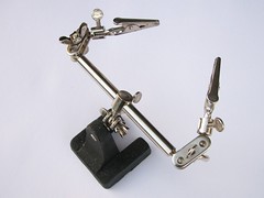
If you are handy with a soldering iron, you’ve probably come across one of these ultra-handy soldering tools. It is various known as a
third hand soldering tool, a set of helping hands, or, as it was introduced to me, as “Mr. Hands.”
Mr. Hands is a great guy to have around for holding a small circuit board or for holding two wires against each other. He provides a third (or even fourth) hand to hold things and prevents your fingers from getting burned. There are all sorts of clever mods that you can perform to them, and they are very cheap– typically $2-$6. You can also make your own equivalent with the same kind of budget, which is good from the standpoint of being able to choose different designs. (I’m partial to the alligator-clips-on-big-fat-wires method, myself.)
The only weakness of Mr. hands is, well, weakness. He’s small, can’t hold heavy or big things, and probably got picked last for kickball. And if it starts to cause a problem, then that’s when we bring out Big Daddy Hands, shown here with Mr. Hands for scale:
Same Bat Holiday, Same Bat Costume!
One year ago, Lenore wrote up her (remarkably popular) umbrella bat costume. If you didn’t build one last year, maybe you want to get started now for this year? In any case, she will be giving a demonstration of how to build it at the Maker Faire in Austin, TX, on October 20-21, 2007.
Interactive LED Coffee Tables: Update and kits!
Cool, our interactive LED coffee tables got a mention in the October issue of Popular Science!
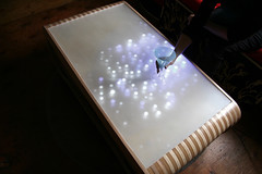
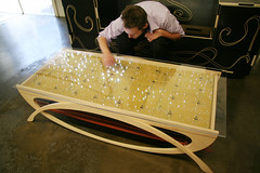
What’s an interactive LED coffee table? (Funny you should ask….) It’s a coffee table that has hundreds of LEDs in the top surface that respond to motion above the table. We have (finally) put together a movie to give you a better idea of how they respond to their environment. You can see the movie on YouTube or watch it embedded:
The complete tables are for sale from Because We Can, our partners in design on this project. There are presently two models, The Ripple (left) and The Wave (right):
Since we first showed these off, we have had a lot of inquiries about how you can make your own table like this. We are now producing (very large) electronic soldering kits so that you indeed can make your own.
Our kits include the giant printed circuit boards, components, instructions, LEDs, and all other parts needed to build the electronic portion of the table tops. Constructed, you end up with what essentially amounts to a single extra-ginormous circuit board that can sit underneath the clear or frosted glass (or plastic) top of your own table. Interesting in getting a kit? Click here to read the details!
(Revised 11/16/2007).
Badass High Vacuum Preparation Oven
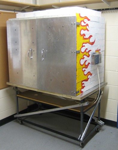
My friend Jeff is responsible for this masterwork of laboratory instrumentation: the Badass High Vacuum Preparation Oven. Physics geeks can read the thrilling details here.
Jeff is really onto something here. More people would want to be physicists if Badass-Compliant Engineering were more common for everyday lab work.
What (the heck) is it?
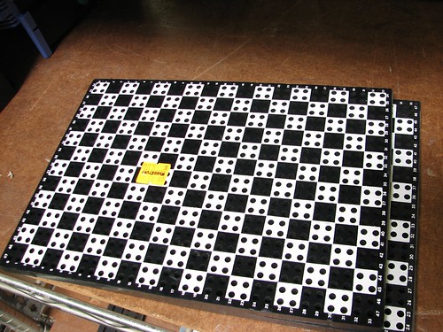
We came across this puzzling object at Weirdstuff, and we haven’t figured out what it is and/or was part of.
The piece is made of stiff black plastic– like that used to make dominoes– and is approximately 3/8″ thick. The surface of the piece is filled with a rectangular array of uniformly spaced holes that are visually labeled with a white checkerboard pattern. Each square on the checkerboard covers four holes and is roughly 1 cm square (we did not take a ruler to it). The rows and columns of holes– not checkers– are labeled. The rows are numbered from 0 to 33, increasing from top to bottom. The columns are numbered from 24 through 47, going right to left. The row labels appear on both the left and right sides, and the column labels are also repeated on both sides. That, combined with the coarser size of the checker pattern would seem to indicate that its usage requires either (1) rapidly identifying the numeric coordinates of a given hole or (2) rapidly finding a given hole from given numeric coordinates.
So what is it? (This time we really don’t know, so your best guesses, hints, and spoilers are welcome!)
Update 9/24/07:
Still no definitive answer. A few more details noted upon a closer look: The holes are clear through the plastic, with no electrical parts, connectors, or contacts inside– it’s just a sheet of holey plastic. The checkerboard pattern and numbering are repeated on the back side of the panel.
Visualizing image stabilization
Last month I went outside at 3 AM to photograph the eclipse. But I ended up having a hard time getting a good picture of the moon. The pictures were turning out unreasonably blurry– much more than I’d expect from just the moon’s apparent motion during the exposure time. The problem turned out to be the “IS” in my Canon S3 IS– the image stabilization– which apparently needs to be turned off for this sort of thing.
But why? Isn’t image stabilization supposed to take out blur?
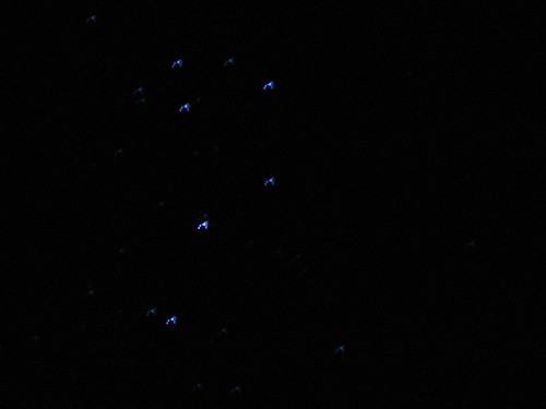
Pointing elsewhere in the sky, you can sometimes (depending where you live) see small point-like sources of lights that can provide a useful tool for figuring out what the bleep your camera is actually doing. In the land of moderate light pollution one thing that we can see through our electronic viewfinder is the Pleiades star cluster, so let’s point our lens at that. The parameters for the two photographs below are identical, except that they were taken with image stabilization off and on, respectively: 15 second exposure, aperture wide open, zoomed in like crazy.
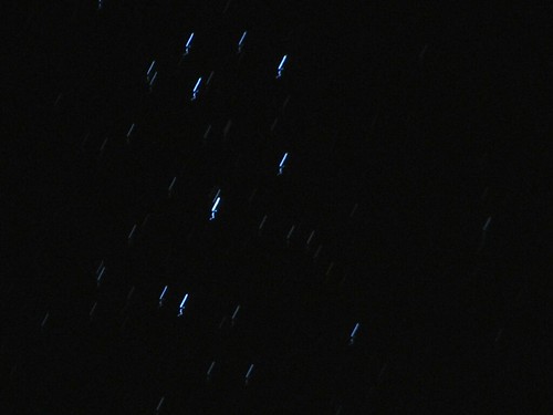
In the top photo the stars each look like clean, easily distinguished stripes.
(In order to reduce vibration due to the button press, these two pictures were taken with a timer delay of a few seconds. However, there is still a small, squiggly tail at the base of each star track, presumably due to residual vibration of the tripod.)
In the lower photo, with image stabilization turned on, you can really see a significant difference. The initial squiggly tail at the lower left of each star track is still present, but is now smaller– thanks to the IS no doubt. Otherwise, the shape of the tracks is quite different. Let’s zoom in:
At the lower left is the initial squiggle from the tripod. In the middle is a large almost triangular structure where the star light was initially steered to. Then, there is an additional, wandering shape starting towards the upper right that bends down the right side.The net effect is that the trail of the star is not reduced to a point– just bent around into a loop.
Conclusion? It looks as though the image stabilization works well for short times– maybe up to a second– but lacks accuracy for longer exposures. And *that* is why you might want the IS off to take a clean picture of the moon.
Update: From what I can see online, there’s no image processing component to the image stabilization process– it’s based solely on sensing acceleration of the camera. Possible answer: Could the slow wandering of the image result from noise in the accelerometer signal?
One Minute Project: Chip Bugs
If you work with electronics, you have probably at some point come across chips that have gone bad. The usual strategies to deal with these include (1) writing “DEAD?” on them in large letters (2) throwing them out, and (3) hiding the evidence. I once heard about a lab student who, whenever he came across a dead chip in his circuit, would dutifully file it back in the drawer with the new chips of that variety– just in case it turned out to be good after all.
Here’s an alternative solution: Turn your chips into Chip Bugs: cute, tiny sculptures that leave no doubt as to which components are which.
Continue reading One Minute Project: Chip Bugs