All posts by Windell Oskay

About Windell Oskay

Co-founder of Evil Mad Scientist Laboratories.

Digi-Comp II: First Edition

dcii_9

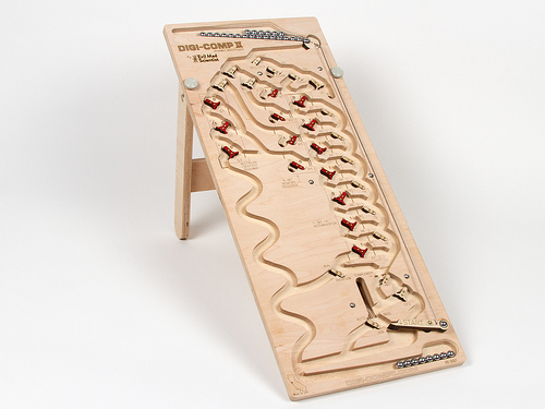
We’re pleased to finally announce availability of our brand new, long-awaited kit, the Digi-Comp II: First Edition. It’s a modern, fully-operational recreation of the original Digi-Comp II— the classic 1960?s educational computer kit —CNC routed from hardwood plywood.

The Digi-Comp II is a binary digital mechanical computer, capable of conducting basic operations like adding, multiplying, subtracting, dividing, counting, and so forth.  These operations are all conducted by the action of balls rolling down a slope, directed by mechanical switches and flip flops, and all powered by gravity.

We’ve been working on project for over two years now, and so we’ve written before, in some detail, about how the Digi-Comp II works, and what kinds of things you can do with it. We’ve written about our larger than life version of the Digi-Comp II, which uses 8 Balls.  We showed off that version at the 2011 and 2012 Bay Area Maker Faires and made a demonstration video to show how it works.   We have also written about our smaller wooden prototypes that we displayed at the 2011 Maker Faire New York.
 

dcii_2

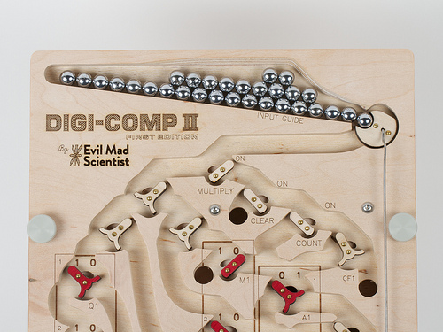
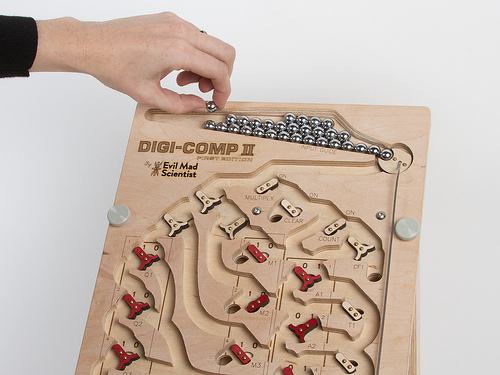
Our new version, the “First Edition,” is a descendent of the latter.  As compared to the “2011” model, it has a huge number of refinements— including an improved ball feeder that both fits 30 balls at a time (so you don’t need to refill during most calculations) and is jam resistant, a more compact and reliable start lever, better labeling, better flip-flop design, and internal baffles that slow the balls down, to prevent them from flying out of the machine.
 

dcii_10

Many of these improvements were made possible by slightly reducing the size of the balls that we use.  Whereas the “2011” model used ½” ball bearings, the First Edition uses standard 11 mm pachinko balls, which are easily available, shiny, and rust resistant.  The fact that they are slightly smaller has allowed us to shrink some of the main circuitry, to allow for that larger ball feeder, to use thinner flip flops, and to fit the full machine into the same 10×24″ envelope that we had aimed for, which is considerably more compact than the 14×28.5″ size of the original.
 

dcii_3

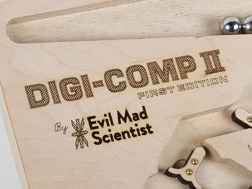
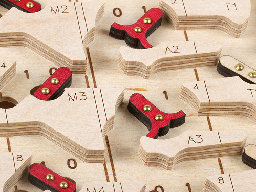
One of the nice things about keeping the size under 24 inches long is that we can fit the entire top deck of the Digi-Comp II into our 12×24″ laser engraver— so that we can directly laser engrave markings onto the playfield.  And while it’s nice to be able to write out DIGI-COMP II in huge letters, the more important application is actually adding the individual markings by the flip-flops and registers:
dcii_6

You may notice that the laser marks are very sharp on the “mesas” of the playfield, and less sharp but more bold down below.   This is an intentional effect, created by laser engraving the playfield in a single pass, with the laser focussed just below the level of the “mesas.”  On previous versions, we’ve either lasered the two parts independently, fully in focus at each depth, or focussed the laser halfway between the top and bottom— which leaves the engraving to look uniform, but less sharp, at each depth.   But this method seems to create exactly what we want:  sharp up top where it’s easier to read, and bold down below where it’s harder to see.
 

dcii_5

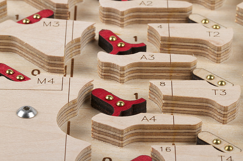
The playfield itself is made of 1/2″ thick maple-faced veneer-core all-hardwood plywood.  This is a rock-solid material that is about as far from “hardware store” plywood as you can imagine.  We use a CNC router to cut the pivot and limit holes for the flip flops and to carve the channels— roughly 3/8″ deep —where the balls can roll.  The CNC router is precise enough that when we cut the channels for the balls, we evenly split one of the veneer layers, ending up with a clean inner surface.  The Digi-Comp II also has a lower deck, below the playfield, that supports the clear-register and complement functions.  The lower deck is carved in the same way, but does not have any laser engraving.
 

dcii_12

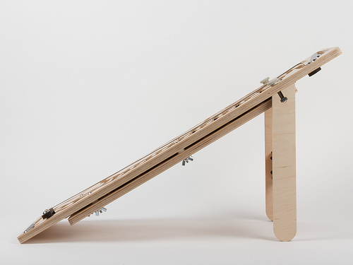
The lower deck is attached below the upper deck by six screws that come down from the top to meet six wing nuts below.  Between the two layers are 3/16″ spacers that keep the decks uniformly separated.  It turns out that it’s actually important to use six screws; our earlier prototypes tended to jam up when the spacing between the two layers wasn’t controlled well enough.

One of the other improvements is that the “First Edition” kit has a very sturdy stand, as shown above.  The laser-cut stand on the “2011” model was flimsy, and the simple dowels on the original 1960’s kit were not much better.   The new stand is a glued assembly made of two rigid legs and a crossbeam, made of the same remarkably-hard plywood as the rest of the machine.  It can be attached to or detached from the playfield with the two fat thumbscrews.  It holds the playfield at an even 30° from horizontal, such that the top sits about 12 ½ inches above your desk top— a particularly good angle for viewing the playfield.  The stand is actually reversible, so that you turn it the other way and raise the playfield only about 20° from horizontal, giving the option of a slower speed of operation.  If you want to go faster instead, you can overclock the Digi-Comp II by putting a book below the stand to increase the angle.
 
dcii_1

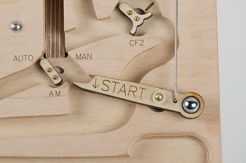
The new ball release mechanism has been fine-tuned and greatly simplified.  We recently showed off a little video demonstrating how this part of the machine works.  The start lever— now nicely labeled —is made of laser-cut poplar, has a brass rivet as its bearing and a glued-in pachinko ball as a counterweight.  When pulled down by a human or a rolling ball, it pushes a stainless steel rod that moves the ball release at the top of the machine to release the next ball.
 

dcii_11

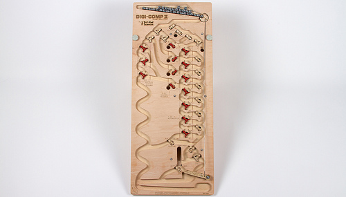
Finally, it’s worth noting that this is called the “Digi-Comp II: First Edition” for a reason: We are planning others.

The original 1960’s Digi-Comp II kit was made of thin vacuum-formed plastic (what we more often refer to as “coffee drink lid material”), supported by a sheet of masonite and fitted with injection-molded flip-flops and switches.  Our CNC-cut wooden versions are much more substantial, but also cost a lot more to make, both in terms of raw materials and fabrication time.  We’ve been slowly working towards what we hope will be a happy medium: a Digi-Comp II made of (more substantial) vacuum-formed plastic, reasonably sturdy, and at a more modest cost.  We still plan to release a version like that, hopefully within the next year.  This has been a long journey for us— making wonderful machines mostly because they are wonderful machines —and we’re very happy to release our first one into the world.


The Digi-Comp II: First Edition is now available to order at the Evil Mad Scientist Shop.

Atkinson Dithering, Live in Processing

resist1_500

Once upon a time in the 1980’s, computers had 1-bit displays, and the world was in (at least, so we understand from the pictures) gray scale.  Those grays were often represented by various types of dithering patterns, of which one of the most classic is Atkinson Dithering.

Atkinson Dithering is named after Bill Atkinson, the developer of classic Macintosh applications MacPaint and HyperCard, where this type of dithering contributed heavily to the look and feel of computer images in the era.

There are already a number of neat applications (listed below) that can perform Atkinson dithering on source images.  Today we’re releasing a neat little Processing sketch that takes video from your webcam and performs Atkinson dithering on it in real time, to produce live video continuously processed with the effect.

zener_500
Screen shot: Zener grudgingly sits in front of the webcam for dithering.  With Atkinson dithering, grays and detail are preserved well, but bright and dark regions tend to be washed out.

The net result is quite surprising, because dithered images like these feel like they should only exist in an era long before webcams and computer video.  And yet, they move.

The Atkinson dithering algorithm itself is a modified version of Floyd-Steinberg dithering, where the “error” between the intended gray level at each pixel and the black or white dot that is actually drawn at each pixel is distributed to neighboring points.

physics gangsign
Windell demonstrates the “right hand rule,” a common gang sign amongst physicists.

There are actually two versions of our “mirror dither”program, at different sizes.  One runs with full resolution in a modern 800×600 window. The other, shown above slightly reduced, is just 512×342, with rounded corners and a black border— giving you live dithered video, the same shape and size as an original Macintosh screen.

You can download the two versions of our program here.  The program is a “sketch” file that runs within Processing, which you can download here for your operating system.  (We’ve written and tested it under Processing version 2.0b6; other versions may work as well.)

And as we mentioned, there are also already plenty of good applications that perform Atkinson dithering for still photos:


Alpha Clock Five v2.0 and Alpha Clock White

Alpha5v20

Today we’re releasing a major update to Alpha Clock Five, our alphanumeric LED desk clock, alarm clock, and data display device.

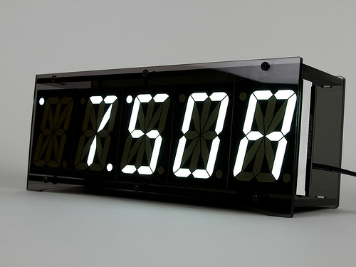
Alpha Clock Five still has five remarkably bright, remarkably huge 2.3″ alphanumeric LED displays.  But for version 2.0, we’ve rewritten the firmware from scratch.  It’s packed with new features and it is simply a joy to use.

To name a few of those new features, Alpha Clock Five now:

  • Has a built-in calendar function so that it can smoothly alternate between displaying the time and date— a neat trick for a desk clock.
  • Smoothly fades between numbers (or letters) on the screen.
  • Has a five letter word “art clock” mode where it displays randomly chosen five-leter words from a built-in dictionary.
  • Allows you to use the second hardware serial port to daisy-chain multiple Alpha Clock Five units together for text or data display applications— for example, as we have done in the photo above.


And, here is one more thing that we’ve been cooking up for a long long time:A5WhiteBrightness-high

The all-new White Edition of Alpha Clock Five— with five 2.3″ alphanumeric LED displays, now in stunning white.   (And, shown above with a phone for scale.)


Alpha Clock Five firmware v. 2.0 is now shipping on new Alpha Clock Five kits, and is also available as a download and free update for anyone who already has an Alpha Clock Five with the original firmware.  Please see our documentation wiki for details.

Read on for more about what’s new in Alpha Clock Five v. 2.0, and about the design of the White Edition.

Continue reading Alpha Clock Five v2.0 and Alpha Clock White

A Peggy 2 Word Clock

Evil Mad Word Clock

Justin Shaw of WyoLum recently presented with this little slice of awesome: One of our own Peggy 2 kits, adapted into a great big “word clock” with the help of custom software and laser-cut acrylic.

WyoLum is a small but international collective of Open Source Hardware enthusiasts who collaborate on hardware designs and other projects (like their Open Hardware Grants) that promote Open Source Hardware.   One of their great ongoing projects has been a series of open source word clocks, ClockTHREE and ClockTHREEjr, which drew inspiration from a number of sources including QlockTWO, Doug Jackson’s word clocks, and the open source design of our Peggy 2 kit.

This is, of course, one of the great things about designing Open Source Hardware: seeing unexpected uses. When we first released the Peggy 2, we didn’t even remotely consider that others would later use our circuit diagram for tips on building their own RGB word clocks.  And now it’s especially neat to see it come full circle, with the ClockTHREE software adapted to work back on the Peggy.

WyoLum’s design files for the Peggy 2 word clock are available for download here (by kind permission), and if you’re building one, you may also find helpful the ClockTHREE repository and our own documentation page for the Peggy 2.

Photo by Brian Krontz of WyoLum.

Photos from the Shuttle Flyby

The crowd at NASA Ames waiting for Endeavour

This morning, we were on hand to see the Space Shuttle Endeavour make a low pass overhead, atop its Shuttle Carrier Aircraft, at NASA Ames Research Center.

As you can see in the panorama above (or at least, as you can see if you zoom in), we were deep in the crowd, out on the tarmac of Moffett Field, surrounded by the tower, Hangar One— presently stripped of its wooden exterior —and far off on the right, the two other blimp hangars.

Shuttle 009

The event organizers apparently hadn’t thought to announce it when the shuttle was getting close, and with the hangars, buildings, and crowd, we couldn’t scan the horizon either.  However, we figured out one way of telling when the shuttle was getting close: When the folks in the control tower started pointing and taking pictures.

The next thing that we saw was a pair of fighter jet escorts. And then, the main attraction:

Shuttle 008Shuttle 007

And what a view!

This modified 747 NASA Shuttle Carrier Aircraft (there are two) has tail number N905NA.  It’s been doing this for a long while— here is a photo from 1978 —but this is one of its final missions.

Shuttle 004

From here, after 25 missions into space, Endeavour moves onto retirement at the California Science Center in LA; perhaps we’ll see it again someday. But, alas, never airborne.

The Art Controller

Art Controller

Today we’re releasing a new open source kit: A stand-alone, microcontroller-driven relay module called the Art Controller.

The Art Controller project was originally suggested by our friends (and Maker Faire regulars), San Francisco Bay Area kinetic artists Christopher T. Palmer and Nemo Gould.  Amongst other things that they build are amazing mechanical sculptures that need to run for a little while after a visitor presses a button or inserts a coin into the slot.

The long-established solution for driving electronic artwork (along with many similar endeavors) is to use a timer relay module; a little stand-alone board with a relay controlled by a timer.  There are several types of these: fancy programmable modules, bulletproof industrial types, and simple low-cost boards with a 555 timer and a pot that you turn to adjust the delay.  As we understand it, Christopher and Nemo go through the latter type like jellybeans.  But, what they realized that they really wanted was something just like that, except that you could reprogram it if you wanted to.

Art Controller

Hence the Art Controller.   It’s a low cost stand-alone relay module, with an on-board AVR microcontroller, an ATtiny2313, that manages the timing and I/O.

It can be used as a replacement for one of those basic 555-based relay boards, but it’s considerably more flexible in terms of timing range and functionality:

  • The timing is adjusted with an 8-position DIP switch, rather than a knob.  This cuts down on guess-and-check, but also gives a huge range. With those 8 little switches, you can select times from 1 second to 31 hours. (The ranges are 1-31 seconds, minutes, or hours, plus a few intermediate ranges.)
  • It can work as a one-shot timer or a continuously repeating timer.
  • There’s an option to trigger automatically upon turn-on (reset).
  • There’s a separate cancel input, so you can build a “STOP” button.
  • There’s an option to cancel a trigger if you push the “START” button a second time.

It comes preprogrammed, and all of those adjustments can be done with switches and wiring— handy if solder is your favorite programming language —so no computer or programming are actually required to get that far.

But, when that’s not enough, the on-board microcontroller can be reprogrammed in situ (using the board’s AVR ISP programming header) to handle the most specialized applications, potentially taking advantage of up to 16 free digital I/O pins.

And that’s pretty neat. 

Art Controller

Beyond the obvious applications in DIY projects, automation, and controlling art projects, we think that this is also going to be a fantastic relay board for education. It starts out as a (well-designed) simple function timer relay board, but can optionally transition to a full-on microcontroller development board when you’re ready for it.

So that’s the Art Controller in a nutshell: a versatile, easy to use, low-cost relay board that you can reprogram if you want to.

There’s plenty more detail on our product page: The Art Controller at Evil Mad Science.

And, special thanks to Christopher T. Palmer and Nemo Gould for a great project idea!


This post is included in our Halloween Project Archive, where you can find ideas for props, decor, and more.

Mailbag: Hacking a Mega-Peggy

grayscale

Tony writes in with a question about hacking our DIY LED matrix kits:

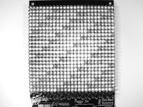
“I’m building a Peggy 2LE. I have completed the wiring with the exception of the LEDs. I have constructed an external frame which has 600 mounting points for my LEDs using a Matrix design of wires crossing every 3 inches. Since the Peggy 2LE has 625 LEDs I need to know how I can drive the 30 anode connections and 20 cathode connections to the wiring them to the Peggy 2. Or am I going to have to wire each LED to the PCB of the Peggy + and – LED locations?”

And, that’s actually an interesting topic.  We’ve written before (here and here) about some giant-scale variations and modifications to our Peggy 2 and Peggy 2LE LED matrix kits, but we haven’t really addressed how one might go about building it.

First off, since you asked— and though we recommend against it —it is indeed possible to build an off-board LED matrix by simply running individual running wires from every LED location on the Peggy circuit board to every LED.  There are 625 LEDs in a 25 × 25 grid, and if each has two wires… that turns out to be quite a few wires.

MakerFaire2011 - 144

While *ahem* labor intensive, this method does work. We know this partly because several people have actually done it.  The “rats nest” of thin, red-lacquered magnet wire shown above is one example, and the Peggy shown here is another victim example of this method.

Fortunately, very fortunately, there are easier ways: think 50 wires, rather than 1250. And, there are a few other clever tricks that you might want to consider when changing the size of the matrix.  For example, it’s possible to use the Peggy 2LE to drive an off-board LED matrix of size up to 25 × 32 without adding any other extra hardware.

Continue reading Mailbag: Hacking a Mega-Peggy

Build Your Own CNC Workstation Cart

CNC Workstation 1

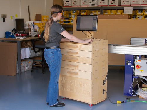
Recently we needed a sturdy, standing-height computer workstation for our workshop. So, we designed and built one. It has turned out to be one of the most useful things that we’ve ever made. And now, we’re releasing our design, so you can build one too!

A little background: This computer station is the one that we use to operate our CNC router.  Previously, we had been operating that machine from a laptop on a rolling tool chest.  While having a tool chest handy was great, the laptop wasn’t, and the height was backache-inducingly awkward.  Once we swapped the laptop out for a desktop computer that didn’t fit on the tool chest, we needed a new solution.  We needed a new computer workstation that would actually fit the computer, be comfortable for working at standing height, be sturdy enough for use in the workshop, roll where we needed it to, and offer a decent amount of storage space for tooling and supplies.

Our workstation is CNC-cut from half-inch plywood. It is rock-solid sturdy, yet comes apart easily for transport or modifications. It features a main computer bay with an optional door, five spacious drawers that can’t fall out, enough room on top to comfortably fit a laptop (in addition to the main computer), stainless hardware, polyurethane casters, and a stiff vertical “neck” that supports a swing-arm VESA monitor mount for the main computer.

Continue reading Build Your Own CNC Workstation Cart