All posts by Windell Oskay

About Windell Oskay

Co-founder of Evil Mad Scientist Laboratories.

Hershey Text: An Inkscape extension for engraving fonts

header-fonts2

Hershey Text is an Inkscape extension that can render a line of text in one of several stroke-based “engraving” fonts. This extension solves a persistent problem, and one which we have come across in many different contexts: How to easily create simple and readable vector representations of text.

Quick start: Download and install the EggBot extensions for Inkscape, which now include Hershey Text. Much more information follows.

Continue reading Hershey Text: An Inkscape extension for engraving fonts

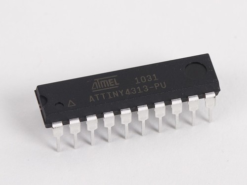
The 4313 has landed.

ATtiny4313-PU

One of our all-time favorite chips is the ATtiny2313.

It’s a little 20-pin AVR microcontroller that we’ve used in dozens of projects, including our high tech holiday decorations, some of our coolest pumpkins, our (digital) Larson Scanner, and some wacky papercraft— to name a few. It’s one of those few chips that we used often enough to justify a custom breakout board.

But… if there’s one thing that the ‘2313 is short on, it’s memory. With 2 kB of flash (program) memory and 128 bytes of RAM, it’s perfect for tiny single-purpose projects. But, it’s oh-so-easy to run up against that memory limit. And, that’s why we were so excited when Atmel began to announce their then-forthcoming ATtiny4313 in late 2009.

Unfortunately, it’s often a long delay between when a chip is announced and when it’s actually available through distribution. Sample quantities have been floating around for half a year or so, but– and finally— a big box showed up in the mail, and so here they are.

4313 - 3

Now, programming it. There are very few changes between the ‘2313 and ‘4313. Mainly, it’s what you’d expect: memory sizes (Flash, SRAM, EEPROM are all doubled), and the device signature is different.

Recent versions of AVR-GCC already support the ‘4313, and so it’s relatively straightforward to recompile an existing program (say, the Larson scanner firmware) to run on the ‘4313. There are some minor inconsistencies between the “io.h” header files for the two chips, and those inconsistencies can cause compiling to fail. For example, the register name “WDTCSR” (for watchdog control register) works on the ‘2313, but the ‘4313 io.h file lists that same register name as “WDTCR.” So, if you run into a place where AVR-GCC is confused after switching chips, you might be able to solve the issue by comparing that register name in the “io.h” files for the two chips.

Now, for programming the chip with avrdude, things are slightly more complicated. Avrdude does not yet natively support the ‘4313, but fortunately, you can add the new chip definition by editing the avrdude.conf file on your system. (On my Mac, where I use Crosspack as the AVR toolchain, I found that file at /usr/local/CrossPack-AVR/etc/avrdude.conf ) The ‘4313 code block can be added right below the ‘2313 code block, and you can download that code block here (via this mailing list post). So, a couple of steps, but works like a charm.

There aren’t a whole lot of these to go around right now, but we’ve put some of our ‘4313 chips into little dev kits that you can pick up at our store. Let’s see how long they last. ;)

Make Live

Becky and Matt

We’re looking forward to today’s premier of Make: Live, a new live web show hosted by Becky Stern and Matt Richardson. The show will feature show and tell DIY projects from guest makers and hackers– and we’ll hope to be amongst those guests in an episode later this year.

The first episode is Arduino focused, and features two (more) remarkable friends of ours: Steve Hoefer (of rock-paper-scissor-golve fame) and Collin Cunningham (of Make Video fame). Steve is bringing his Secret Knock Gumball Machine, and Collin will be discussing his MidiVox shield for Arduino.


The show runs live Wednesday January 26th, 9 PM Eastern / 6 PM Pacific, and you can see it at makezine.com/live or on UStream.

(And, if you can’t catch it live, they’ll be archiving it on their YouTube channel and iTunes podcast. We’ll post direct links to those when they’re available.)

Update: You can subscribe to the MAKE Podcast in iTunes, download Make: Live episode 01 in its entirety (m4v), or watch clips on YouTube.

The next episode, “Make: Live 02 – The Soldering Episode,” runs
Wednesday February 9th, at 9 PM Eastern / 6 PM Pacific

AVR Basics: Reading (and writing) flash contents

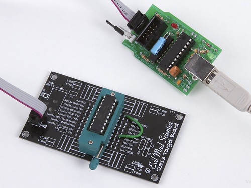
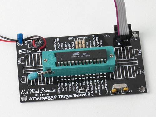
Programming on a target board

From our forums comes this interesting question:

   “Is it possible to download the contents of an ATmega168/328, essentially backing it up so that it can somehow be restored later?

For example: Let’s say I have lost the source code to a very useful program currently residing on a 328, but I need to flash it with a different sketch temporarily, then restore that original sketch. This would be useful in the case that the chip was soldered directly onto a board – a big mess to try to replace.
Is this possible in some way, perhaps by altering an ISP programmer?”

The answer is that yes indeed, it is possible– with a couple of exceptions that are worth mentioning. And on occasion, it’s even very useful. Continue reading AVR Basics: Reading (and writing) flash contents

The beach glass machine

A guest project by Rich Faulhaber, contributing Evil Mad Scientist.

4 hours -detail 2

“Walking the beach with the kids, one of our favorite pastimes is collecting shells, bits of sea glass and other rocks. We typically put them in buckets, sort them when we get home, and then put them in the garden– except for the few special ones that the kids keep on their dresser.


In the process of making a garden path which stretches 50 feet long and is 2.5 feet wide, I thought, how cool would that look if it were some sort of mosaic of sea glass! Snapping back to reality I realized how much time would be required to collect that much sea glass and got discouraged. But (eureka!) you can make your own. All you need is some glass, some sand, sea water and some way of mimicking the ocean and (bam!) you get sea glass.

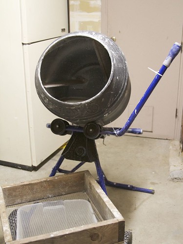
I wanted to do large volumes, so I borrowed my uncle’s cement mixer to mimic the ocean. The steel fins inside mimic large rocks. I started breaking wine bottles into small pieces and stole some sand from the kids play box, adding it all to the mixer. Since I didn’t have any sea water handy I just filled it with tap water and turned it on. After an hour I checked and the sharp edges were all broken off, after two hours there was some frosting and smoothing and after 4 hours et voilà— I had sea glass! With the capacity of the mixer I will have my garden path in no time. I plan on experimenting with other media and time duration and will report on my progress in the future.”

Mixer and screen

An ordinary hardware store cement mixer, tap water, and play sand. Simpler and more environmentally friendly than using many other common abrasives that are used with rock tumblers.

Draining

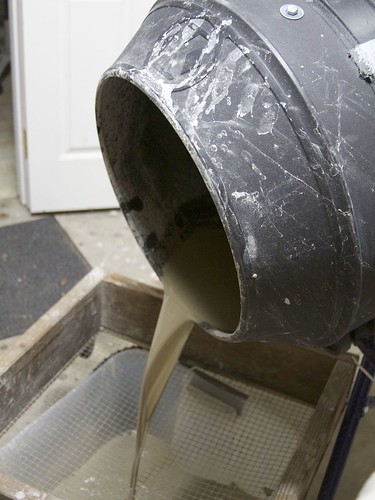
Add glass and allow to run for several hours. After running, drain the excess the sand-water slurry through a coarse screen.

Drained mixer

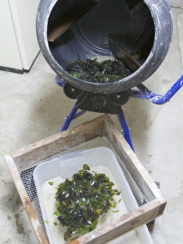
After dumping out the excess and some of the glass.

instant beach glass!

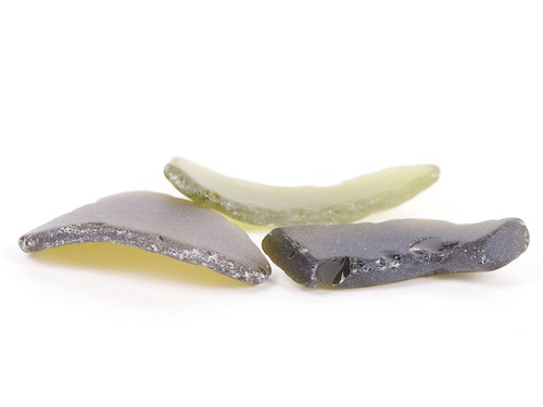
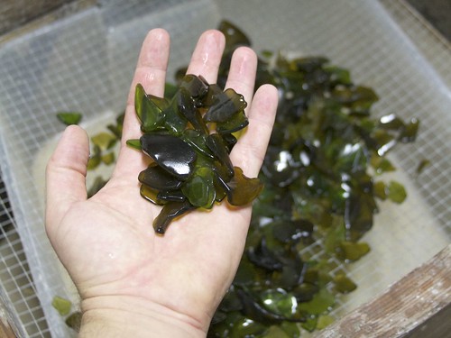
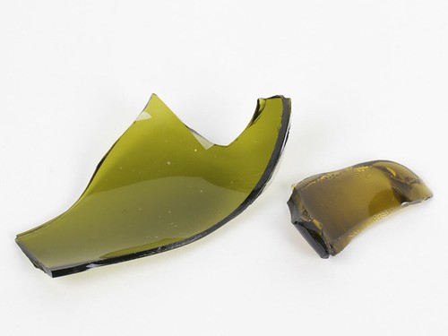
This batch was made with a mixture of broken green and brown glass, mostly from wine jugs, and allowed to run for four hours. Below are some pictures of glass allowed to run for different lengths of time.

Raw


Here’s what the raw glass looks like, zero hours in the mixer.

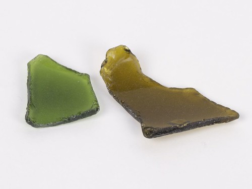
1 hour

These pieces were pulled out after one hour in the mixer. Their sharp edges are broken, and there’s light etching of the surfaces.

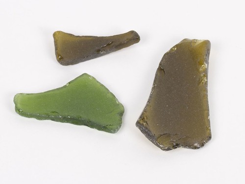
2 hours

These pieces were pulled out after two hours in the mixer. The shapes are slightly more rounded, and the surfaces are beginning to frost heavily.

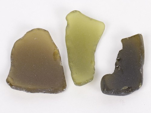
4 hours

And after four hours, the pieces begin to look a lot like what you might find washed up on a sandy beach. While it will be interesting to see how the pieces change over longer pieces of time, you probably don’t want to go too much longer (and wear them too much thinner) if you’re making mosaic pieces for people to walk on.

Ever seen one of these?

whatsit-pcb - 3

whatsit-pcb - 5

whatsit-pcb - 1

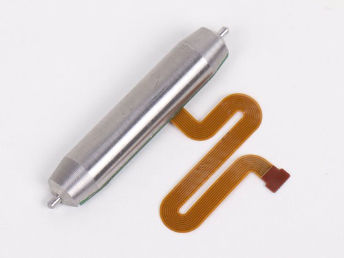
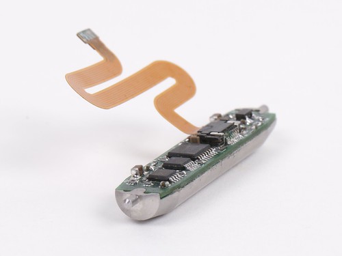
From the files of TGIMBOEJ comes this piece of unusual hardware.

What does it do? Where did it come from? What does it want from us? And why is it shaped like that? An interesting little mystery.

The overall size of the object is about 1.75 inches long. The cylindrical part appears to be made of 300-series stainless steel or a similar alloy. The back side of the circuit board is flat, without any components (yep, pried it up to look).

Now, I’ve found most of the answer already, but I don’t know the manufacturer or specific application. Do you recognize it, or can you guess what it is or what it’s from?

In the pictures here, the chip markings are obscured– that would be too big of a hint. We’ll add clearer pictures tomorrow if no one gets it by then.

Update:

A couple of folks were able to piece it together from the pictures here. On twitter, Henrik Sandaker Palm (@HSPalm)
wrote, “I bet one of those chips are some sort of gyroscope or directional sensor…”

And yes, that’s quite correct. One of our anonymous commenters (and, madam or sir, please stand up and take credit!) explained how they came to the same conclusion:

    “I will guess that this is part of a precision compass based on the following reasoning.

    1. Whatever is on the board is a sensor. A screen driver or other controller would have more than a single eight wire connection, and there are no other visible interfaces. I am assuming that there are no other electronics embedded in the steel block because they looked under the board and didn’t mention any.

    1b. The fact that part numbers would be too obvious implies that at least one of the components is highly specialized. This is consistent with there being a sensor on the board, although there are many other specialized devices it could be.

    2. The board is meant to stay level. There is no good reason to have a large counterweight and flex connector on a circuit board unless it is meant to maintain the board in a level state. There is a good possibility that this was also mounted in a swivel along an orthogonal axis to provide freedom on both pitch and roll (this may be why the flex circuit is S-shaped instead of straight).

    3. The only sensor I can think of that needs to be level is a compass. The sensor could also be an accelerometer provided it was meant to be used while the device was stationary to measure the force of gravity, because movement would cause the board to shift and invalidate the readings. There does not appear to be any encoder components that could take the rotation into account.

    4. This is probably a precision instrument because the counterweight appears to be fully machined instead of cast, which implies it is part of an expensive device manufactured in low quantities.”

Correct on all counts. The particular shape and size of the flex-circuit connector indicates that the assembly is free to rotate a small amount not only in one axis, but in two, as though it were mounted as a compass in a gimbal (like so), with a weight to keep the circuit board level.

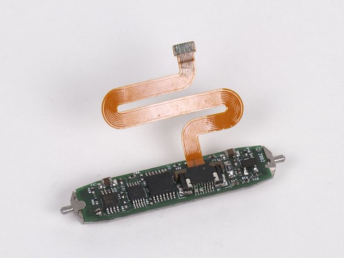
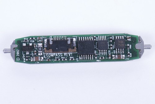
Here’s another picture, now with the flex-cable disconnected, and the chips visible:

whatsit-pcb - 8


Besides the obvious point– that the board is labeled “compass” under there, the second chip from the right is an HMC1052 two-axis compass chip. That’s not so very different from the HMC5843 that we demonstrated in this project.

The remaining mystery is this: exactly what did it come out of?

It would be nice if the manufacturer labeled what it came from. But, we can narrow it down a little bit. As the commenter noted, the machined stainless suggests that it’s part of “an expensive device manufactured in low quantities.” Add to that, (1) a custom flex cable is used rather than just a longer wisp of off-the-shelf flex cable or plain thin wires and (2) the circuit board and stainless are carefully machined so that the board can only fit in one way. Custom flex cables are expensive in low quantity. Engineering parts such that things can only fit together one way is usually done for reasons of precision in mass production. Together these suggest that perhaps it came from something (yes) expensive, but mass produced none the less. The fact that it’s in a gimbal mount suggests that whatever it was originally in moved, for example in a vehicle. The fact that it relies on a weight to operate suggest that it wasn’t designed to operate in zero-g, leaving “only” air, sea, and land vehicles as possible suspects. If you can come up with any other evidence or things to check that might help identify what it might be, we’d love to hear about it in the comments.