Andreif shared this timelapse of building a Bulbdial Clock Kit on twitter:
Bulbdial from
@EMSL completed. Thanks again to@maltman23 &@jprodgers for the terrific solder workshop at@netz39.
Andreif shared this timelapse of building a Bulbdial Clock Kit on twitter:
Bulbdial from
@EMSL completed. Thanks again to@maltman23 &@jprodgers for the terrific solder workshop at@netz39.
We built a evaporating-hand water clock using a WaterColorBot fitted with a Buddha Board. The Buddha Board is a black board with a gray ceramic coating that becomes transparent when wet, so you can paint on it with plain water to make black marks that disappear as the water evaporates. (And, it fits nicely in a WaterColorBot with the appropriate jig.)
As a clock, once a minute it draws the minute hand, then the hour hand, and finally the outline of the clock face.
As the water evaporates over the course of a few minutes, the old minute hands fade away. It’s a neat effect.
And of course, video:
Continue reading A WaterColorBot Water Clock
Today we’re introducing version 2.0 of our “Three Fives” Discrete 555 timer kit. Version 2.0 has a number of little tweaks and improvements, with a cleaner design and — coolest of all — an all-new set of smooth anodized aluminum legs.
The Three Fives kit is a faithful and functional transistor-scale replica of the famous 555 timer integrated circuit — one of the most popular and well-loved chips of all time. (An original NE555 IC is shown above for scale.)
We are also releasing the first version of our educational supplement for the Three Fives kit: A detailed description of how the 555 circuit actually works, with plenty of opportunities for further exploration. You can find it on the downloads section of the product page or on our documentation wiki.
With Maker Faire coming up next week, @techninja42 suggested that Maker Faire Bingo would be a great way to get ready! With the help of some friends, he put together a site where you can grab a bingo card to play during your visit to Maker Faire. We tried it out with the WaterColorBot, but you can use your preferred automated printing method to make your own, or maybe even find a robot at Maker Faire to draw it for the ultimate Maker Faire Bingo!
Send your maker bingo suggestions to @mfbingo for inclusion in the bingo card generator.
Over at Thingiverse, user gkrangan posted this wacky contraption: A machine to write with a stylus on a Boogie Board e-writer, built from PrintrBot Simple frame components, along with EggBot electronics and the pen-holder. It’s driven through the EggBot extensions for Inkscape.
I was initially taping an index card onto the print platform for testing purposes, but when I saw this Boogie Board at a toy store, it seemed like a perfect choice to be used as the writing surface. One can draw/write anything on it, and erase with a press of a button. Of course, it can still be removed and any other suitable surface can be taped or mounted on the print platform, as necessary.
Printer Egg Boogie Board Bot @ Thingiverse
Wes wrote in to say:
I am an Electrical Engineer (graduated May ’72, Texas Tech U), but I never saw or even heard of a homopolar motor until last week, when I saw an electric motor made from four parts on National Geographic’s program, “None of the Above“. When I first saw it, I figured it must be a hoax. A DC motor had to have a commutator and two magnets.
Only when I was browsing around in Wikipedia did I find an article on the motor. I happened to have everything I needed, so I built one, not really expecting it to work. To my great surprise, it spun up to a few thousand RPMs in seconds. I read Wikipedia’s theory of operation, but it didn’t make sense. Today, I came across your wonderfully clear and simple explanation, and now I understand the motor perfectly.
I simply cannot thank you enough for your drawing and explanation.
Thanks for writing in— we’re glad to hear you enjoyed learning something new! The instructions for making the motor and the discussion of how it works are in our articles:
Hey look! It’s the fossilized remains of a possible evolutionary ancestor of the EggBot!
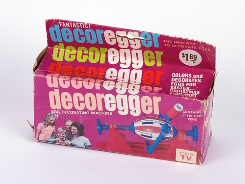
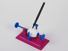
Okay, it’s pre-USB but technically it’s not a fossil. Like many of us, the decoregger dates from the mid-1970’s. It’s a simple function gadget that mounts an egg so that you can spin it, with arm second arm that holds tiny felt-tip pens. Curiously, there are also some contemporary machines bearing the same name that lack the separate arm.
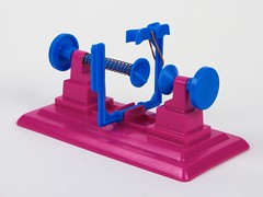
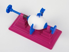
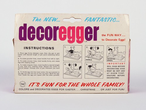
In the upper-left photo, you can see that the pen holder has a separate “paddle” that you hold, to manually move the pen in the arc across the egg surface. Lacking the proper felt-tip pens, we found that a uni-ball micro pen was about the right diameter to fit in the holder.
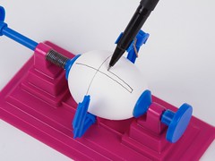
One surprising thing: To model this thing, we used regular “large AA” (not extra large, and not jumbo) size eggs from the grocery store. And it was only barely possible to squeeze the egg into the holders. From the picture on the box, it looks like there’s plenty of room for even the largest egg. Possible explanation #1: Plastic shrinks over time. Possible explanation #2: The egg pictured on the box is from the advertising land of freaky micro-children.
But in any case, the decoregger is a cute little machine, and it looks like it might be fun to play with. The actual play is a matter of turning knob 1 and knob 2, so it feels a lot like an Etch-a-Sketch in spherical coordinates. Now if only there were some way to strap a couple of motors to it and perform a CNC conversion….
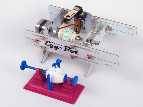
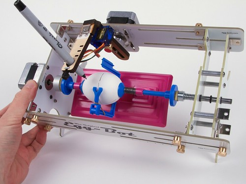
Speaking of which, it really is a lot smaller than the EggBot. Heck, you could probably fit the whole thing inside the EggBot.
Wait — am I doing this right?
Special thanks to Michelle Hlubinka for finding this artifact and sending it to us!
Katherine Scott posted on Twitter:
The
@EMSL eggbot being used for demos by IDS imaging at the@AIAVision show. Awesome.
A minor bump for one of our little open source Arduino add-ons. The Simple Relay Shield is an easy to use single-relay board that does one thing, and does it well: It adds a beefy little mechanical relay to an Arduino, which you control through pin Digital 4.
Version 2.0 adds the ability — by popular request — to control it from a pin other than D4. Solder the jumper in the normal way (in location JP), and it works on pin D4. Hook it up to any other digital pin, say to D7, and now you have a relay on that pin. The Simple Relay Shield is available as a complete soldering kit or as a bare PCB, and you can find documentation on our wiki.