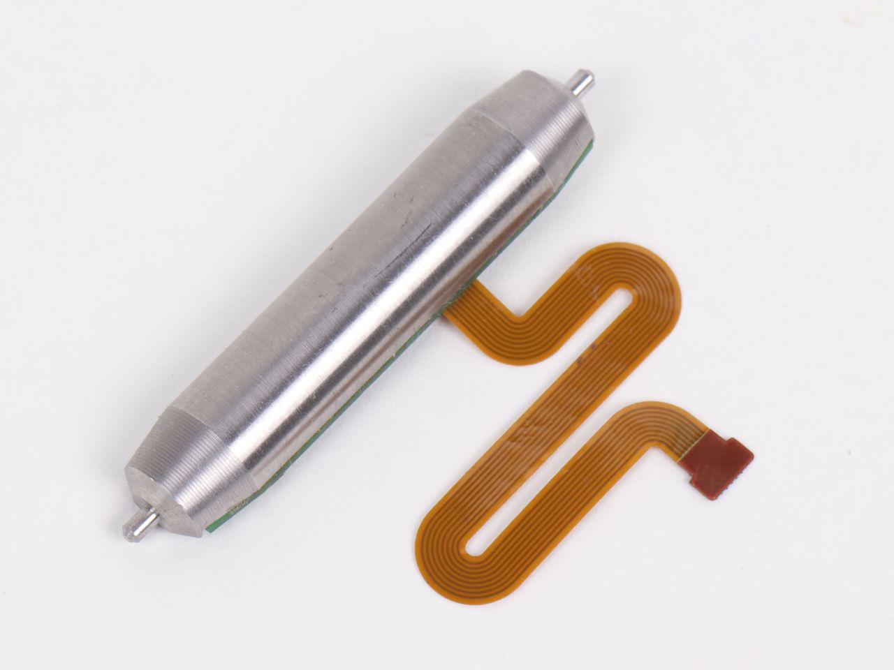
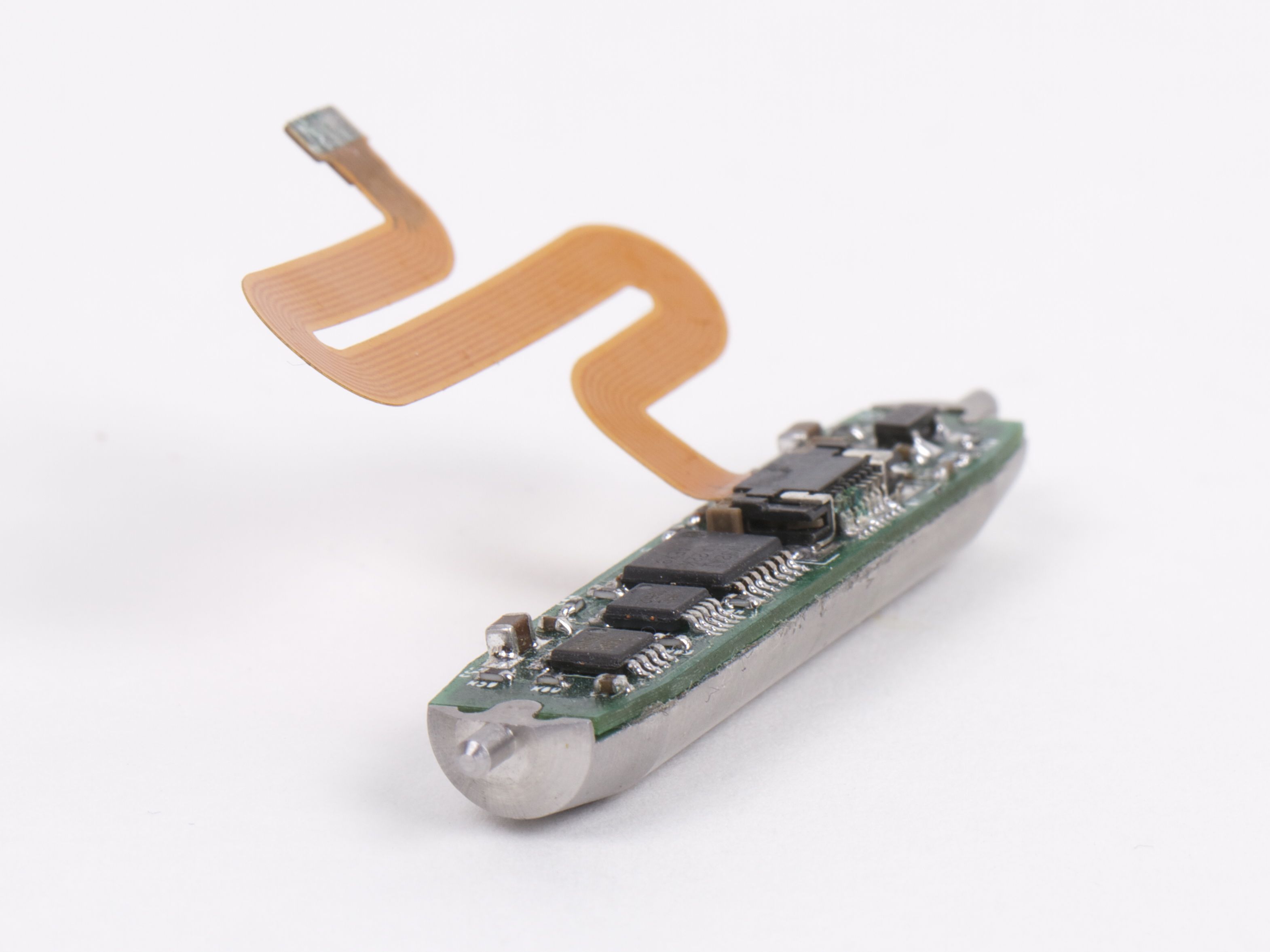
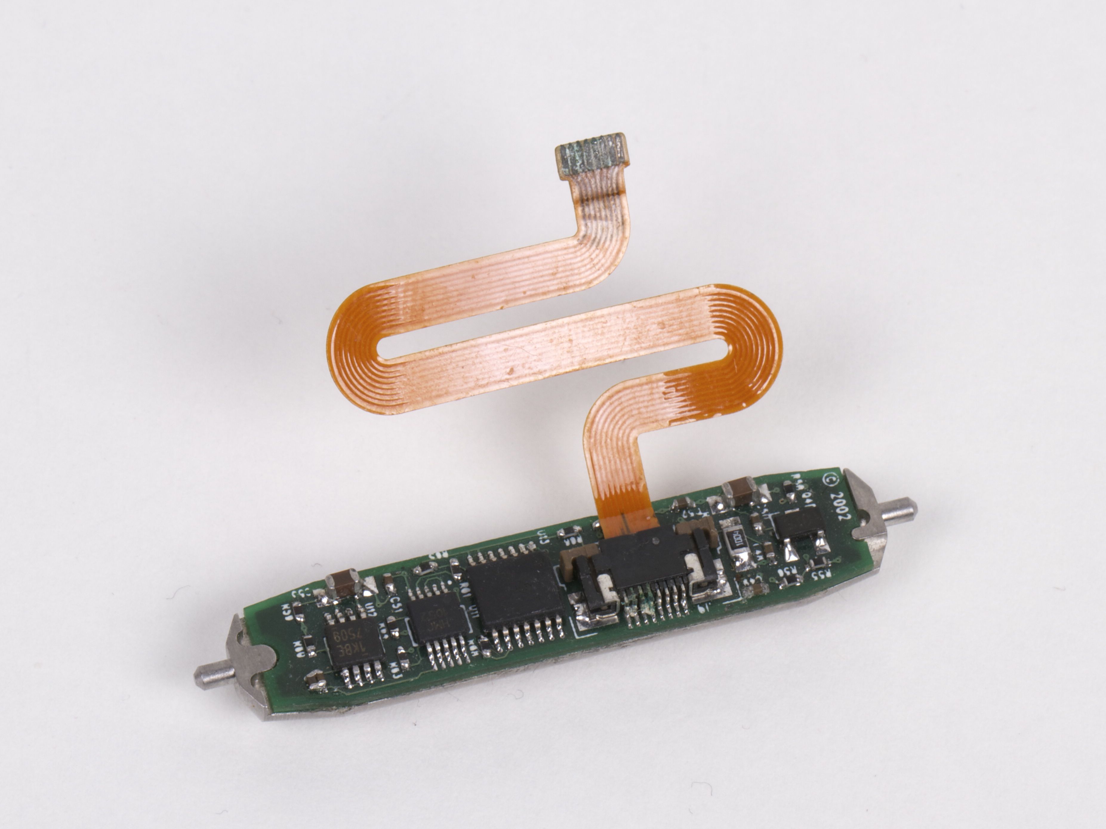
From the files of TGIMBOEJ comes this piece of unusual hardware.
What does it do? Where did it come from? What does it want from us? And why is it shaped like that? An interesting little mystery.
The overall size of the object is about 1.75 inches long. The cylindrical part appears to be made of 300-series stainless steel or a similar alloy. The back side of the circuit board is flat, without any components (yep, pried it up to look).
Now, I’ve found most of the answer already, but I don’t know the manufacturer or specific application. Do you recognize it, or can you guess what it is or what it’s from?
In the pictures here, the chip markings are obscured– that would be too big of a hint. We’ll add clearer pictures tomorrow if no one gets it by then.
Update:
A couple of folks were able to piece it together from the pictures here. On twitter, Henrik Sandaker Palm (@HSPalm)
wrote, “I bet one of those chips are some sort of gyroscope or directional sensor…”
And yes, that’s quite correct. One of our anonymous commenters (and, madam or sir, please stand up and take credit!) explained how they came to the same conclusion:
“I will guess that this is part of a precision compass based on the following reasoning.
1. Whatever is on the board is a sensor. A screen driver or other controller would have more than a single eight wire connection, and there are no other visible interfaces. I am assuming that there are no other electronics embedded in the steel block because they looked under the board and didn’t mention any.
1b. The fact that part numbers would be too obvious implies that at least one of the components is highly specialized. This is consistent with there being a sensor on the board, although there are many other specialized devices it could be.
2. The board is meant to stay level. There is no good reason to have a large counterweight and flex connector on a circuit board unless it is meant to maintain the board in a level state. There is a good possibility that this was also mounted in a swivel along an orthogonal axis to provide freedom on both pitch and roll (this may be why the flex circuit is S-shaped instead of straight).
3. The only sensor I can think of that needs to be level is a compass. The sensor could also be an accelerometer provided it was meant to be used while the device was stationary to measure the force of gravity, because movement would cause the board to shift and invalidate the readings. There does not appear to be any encoder components that could take the rotation into account.
4. This is probably a precision instrument because the counterweight appears to be fully machined instead of cast, which implies it is part of an expensive device manufactured in low quantities.”
Correct on all counts. The particular shape and size of the flex-circuit connector indicates that the assembly is free to rotate a small amount not only in one axis, but in two, as though it were mounted as a compass in a gimbal (like so), with a weight to keep the circuit board level.
Here’s another picture, now with the flex-cable disconnected, and the chips visible:
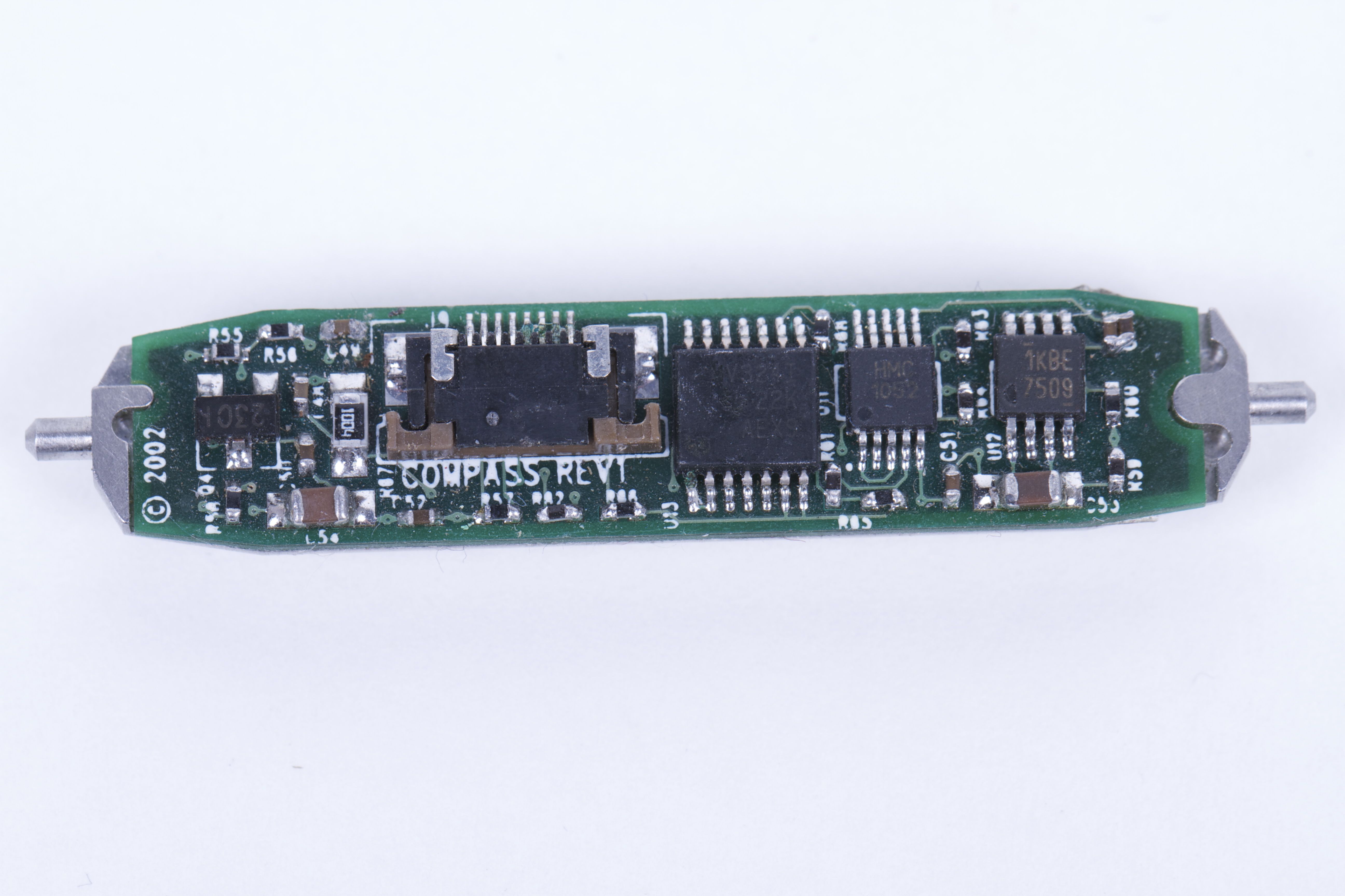
Besides the obvious point– that the board is labeled “compass” under there, the second chip from the right is an HMC1052 two-axis compass chip. That’s not so very different from the HMC5843 that we demonstrated in this project.
The remaining mystery is this: exactly what did it come out of?
It would be nice if the manufacturer labeled what it came from. But, we can narrow it down a little bit. As the commenter noted, the machined stainless suggests that it’s part of “an expensive device manufactured in low quantities.” Add to that, (1) a custom flex cable is used rather than just a longer wisp of off-the-shelf flex cable or plain thin wires and (2) the circuit board and stainless are carefully machined so that the board can only fit in one way. Custom flex cables are expensive in low quantity. Engineering parts such that things can only fit together one way is usually done for reasons of precision in mass production. Together these suggest that perhaps it came from something (yes) expensive, but mass produced none the less. The fact that it’s in a gimbal mount suggests that whatever it was originally in moved, for example in a vehicle. The fact that it relies on a weight to operate suggest that it wasn’t designed to operate in zero-g, leaving “only” air, sea, and land vehicles as possible suspects. If you can come up with any other evidence or things to check that might help identify what it might be, we’d love to hear about it in the comments.


