Category Archives: Electronics

Three Fives in IEEE Spectrum

IMG_6354

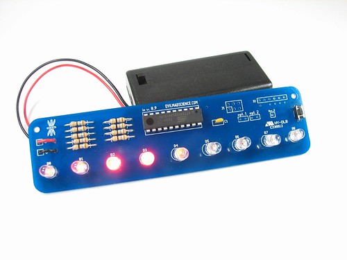
Our Three Fives Kit was featured in this month’s IEEE Spectrum. From the article:

Just as DNA models, star maps, and periodic tables serve as reminders of fundamentals that can get obscured by day-to-day minutiae, so too the Three Fives kit is a reminder that even the most complex digital processor is still at its heart just a collection of very simple components.

You can read the full article and see pictures of it in use in a sample circuit over at IEEE Spectrum.

Basics: AVR Target Boards and Arduino Compatibility

Diavolino
Gary writes:

I have fallen in love with your Diavolinos – thank you!
My question: does the “Simple target board” allow for the 6-pin FTDI Friend hookup to upload sketches? This is quick and easy with the Diavolino. I’m new to reading circuits and stuff, and I cannot tell looking at the target board. It says to use in-system programmer, but I prefer to not buy another interface. Thanks!

Excellent question! It is certainly possible, but not as quick and easy.  Both the Diavolino and our ATmegaXX8 target boards boards use the same chip, usually the ATmega328P.  But, one might say that our ATmegaXX8 board is a simple AVR target board optimized for use with an AVR ISP programmer (like the USBtinyISP), whereas the Diavolino is a simple target board optimized for use with the FTDI interface.

XX8 Target Board

Versus a “bare” target board (with just the chip and power), there are four things that you would normally add, in order to use the FTDI interface to upload a sketch from within the Arduino environment:

Continue reading Basics: AVR Target Boards and Arduino Compatibility

Cool Wearable Electronics

Untitled

Mascot costumes are often hot and sweaty, and mascots are expected to enthusiastically energize their teams. At FIRST robotics competitions, there are also traditions of dance parties during delays caused by technical difficulties, leading to even more activity in a warm, heavy costume than would normally be expected.

Untitled

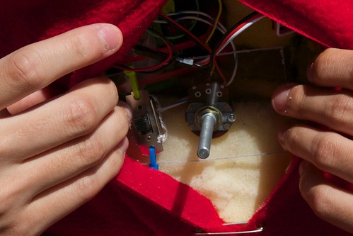
Cardinalbotics, an FRC team from San Francisco, made a mascot costume using an application of wearable electronics I had not considered before: cooling fans. The cardinal head was made of fabric sewn over shaped foam, with fans on the sides to keep everything cool inside.

Untitled

The fans were wired up to an on/off switch and adjustment pot which were hidden in a velcro compartment in the back of the head.

Larson Scanner modding

larson3

Anton wrote in to ask:

I want to purchase your Larson Scanner kit but need to be able to run it from household current … is there a converter that you would recommend?

Since the Larson Scanner normally runs from 3 V DC, a regulated 3 V power supply can be hooked up in place of the 2xAA battery box. However, 5 V power supplies (like this one) are much more common, and the circuit can be run from 5 V with only minor changes. if you replace the nine 16 ohm resistors in the Larson Scanner kit with 120 – 150 ohm resistors, you can power it from 5 V directly.

Another related question we occasionally get is how to run the Larson Scanner with green LEDs. (Note: by green, we mean “pure” green LEDs which have a forward voltage of about 3 V. Older style yellow-green LEDs with a forward voltage of ~2 V can be used as drop-in replacements for the red ones.) 

If running off of battery will work for you, this is an even simpler change: merely replace the 3 V battery holder with a 4.5 V one, such as a 3xAA. It is a happy coincidence that the circuit can run with red LEDs at 3 V or green LEDs at 4.5 V using the same 16 ohm resistor value. So how about running a green Larson Scanner from a 5 V power supply? Replace the nine 16 ohm resistors with 39 ohm resistors and you should be good to go.

You can find the documentation for the Larson Scanner and more stories about modding it on our wiki. We’d love to hear about any mods you do to the Larson Scanner in the comments or see pictures in the flickr pool.

Resistor Wallet

Resistor Wallets in use

Ben wrote in with a great question:

I had a quick question regarding the Three Fives Kit. First of all I just wanted to say that great job on the kit! I LOVE mine and it was a blast to put together. I just had a quick question about one of the packing items used when the kit is shipped. I loved the resistor organizer/holder you shipped the resistors and have been trying to figure out where to get them. The best I could guess was that they are sewing needle holders, but I have been unable to find them as such.

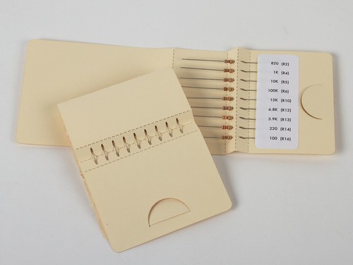
Many of our soldering kits have multiple resistor values, but the Three Fives kit is unusual among our projects in having nine individual resistors of different values. This presented an interesting problem: how to make user friendly packaging to make it easy to find the right resistor. Sure, you can read the color code stripes, but that can be a pain for folks with color blindness or just plain old poor vision.
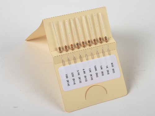
Resistor Wallet in use

Our solution was to design a custom wallet, modeled after needle packets, to hold and label the resistors with their locations & values. The resistors are dropped into slots, secured with a label, the cover flap is closed over them and then tucked under a tab. During use, each resistor is simply pulled out from under the adhesive label.
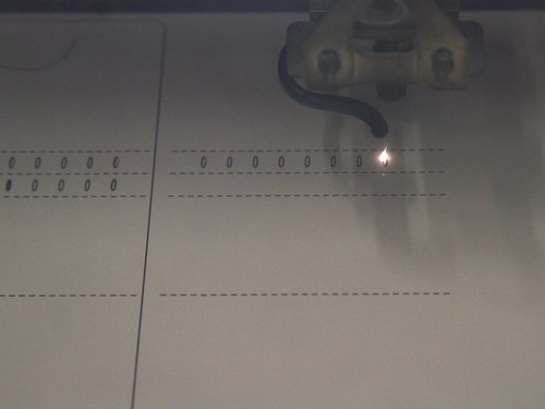
Laser Cutting Wallets

The wallets are laser cut out of sheets of 60 lb manila cardstock. It bends easily along the perforations, but is very sturdy and can withstand many repeated bends. (Aside: this weight is very similar to punch cards, which—to go full circle—is what I use for storing sewing needles.)

Resistor Wallet

We reused the wallet with a different label when we released our multi-colored Menorah and breadboard Menorah kits, which also happen to use nine resistors in a variety of values.
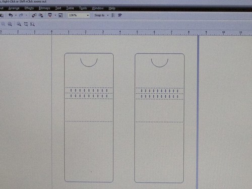
Resistor Wallet Design

Today we’re releasing this resistor wallet design in two versions: one for nine resistors, and one with slightly narrower spacing to hold ten.

If you use our resistor wallet, we’d love to hear about it or see pictures in our flickr pool!

Access Point Garage Door Opener

Over at Dead, too much lettuce., Scott built an Access Point garage door opener with a Raspberry Pi, an Arduino, and our Simple Relay Shield.

I bike to work. Bikes live in the garage. But with only 2 remotes, I could not keep one in my bag all the time to be able to get to the bike. So a new option had to be created. Most people would have bought a new remote…

555 footstool in the wild

555 Footstool: date code 1403

This newly minted (date code: 1403) 555 footstool comes to us via Martin on Twitter, who writes:

My 555 footstools arrived. Build by my father-in-law, based on design files from @EMSL

Here are our original project post and our design.  This is the first time that we’ve seen someone else build one based on our design. Nice!

DIY Electric Kistka for Eggbot

Ann posted instructions in our forums for creating an electric kistka (wax pen) for the Eggbot for traditional Pysanky egg dying techniques. She used nichrome wire, krylon tape, a modified kistka, and a 2xAA battery holder with a switch and described how to mount it in the Eggbot. She posted a couple of designs to Thingiverse demonstrating the technique including the rose design pictured above.

For a Humpty Dumpty design, she wrote up how she made it:

Using eggbot and custom electric kistka, plotted the Humpty Dumpty picture and text on an egg. First plotted outline, dyed brick, colored in bricks by hand with kistka, dyed blue.

You can check out her other designs for the Eggbot on Thingiverse.