Category Archives: Electronics

How Printed Circuit Boards are Designed (1960 Edition)

We found this gem in A Manual of Engineering Drawing for Students and Draftsmen, 9th Ed., by French & Vierck,1960, p. 487.

Printed Circuits allow miniaturization and the elimination of circuit errors—advantages that cannot be obtained by other methods. Once a pattern or suitable design is established, preparation of a black and white drawing can start. Scales for reduction, for example, 4 to 1, 3 to 1, or 2 to 1, are used. To insure sufficient bonding area of the metal laminate during soldering operations, lines should not be less than 1/32 inch in width when reduced. Line separation should never be closer than 1/32 inch on the final circuit. Figure 19.24 illustrates the drawing of printed circuits.

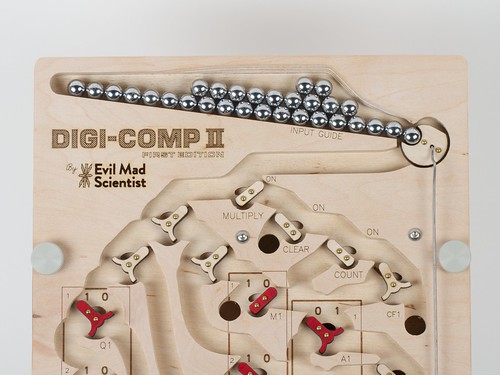
From the Mailbag: On the Digi-Comp II

dcii_2
Peter wrote in about his experience with the Digi-Comp II:

I just wanted you and the entire Evil Mad Scientist team to know that the Digi-Comp II was a big success.  I used it to explain digital computers to a group of second graders and fifth graders. In an age of iPads and smartphones, it’s surprisingly hard to demonstrate the beauty and magic of digital computer.  The Digi-Comp II was perfect, looked great, and worked flawlessly. Thanks!

PCBmodE: Make your PCB a work of art

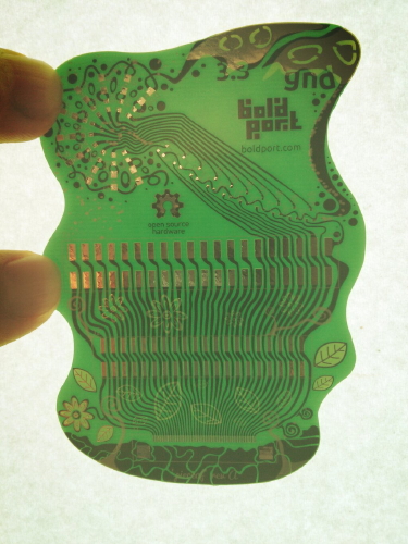
The folks at BoldPort have created PCBmodE, free open source software for designing printed circuit boards, but with an artistic perspective. Traditional EDA tools are designed from an engineering perspective, whereas PCBmodE treats the PCB as a creative palette. They aim to give you freedom to express your design with all the tools of the medium.

We wanted to create circuit boards that have curvey traces, meandering paths, and multiple soldermask layers, so we developed PCBmodE (say “PCB mode”), an open source Python software that unshackle us from the constraints imposed by traditional PCB design tools. We use the power of Inkscape — the leading open source vector graphics editor — to achieve any shape imaginable. Together with our powerful back-end tools, we can manufacturable beautifully functional boards.

They’ve posted about several of their example boards including pieceof (pictured above), a Raspberry Pi daughterboard called shimmy, and a tribute board dedicated to Bob Pease. This is a really neat approach to building circuit boards, and it looks like it has a lot of potential.

Open Discussion: Does Solder Expire?

Solder 4

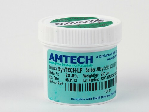
When we recently wrote about looking at solder paste up close, we happened to mention that it has a shelf life— something that you might expect to be uncontroversial considering that there is an expiration date, printed right there on the jar.

But, our reader Trav commented

Very nice pics. What happens to solder paste when it expires? does it taste funny? Do the balls go flat?

I assume the paste rather gets runny and doesn’t hold the solder in place or it gets thick and won’t spread evenly.

I’ve heard of it expiring, but never knew how. I’ve had a tube of flux for 20 years now. When it gets too thick, I put in a couple drops of alcohol and it seems to work good as new.

We like the “balls go flat” theory!  But seriously, we presume that they wouldn’t label paste with a short shelf life— typically 4-12 months, when kept refrigerated, depending on the type of paste —unless there were a reason (and hopefully, a good reason) to do so.

A blog post on the Indium Corporation web site offers a little insight.  It turns out that the “activator” chemicals within the flux, which serve to clean oxides off of the surfaces that will be soldered, also interact with the microscopic solder balls, gradually scouring off their surface oxides.  When the solder particles are clean enough, they can actually cold-weld together, resulting in increased effective grain size and viscosity.  As Trav notes, adding a little alcohol can reduce the viscosity of flux, but we can see how increased grain size and other factors (such as having used up some of the activators) could affect performance in other ways.

But in any case, it sounds like there are a range of experiences out there, and we would like to open the question for discussion: What has your experience been with out-of-date solder paste? Has it worked just fine? And if not, what was the failure mode?
 

Solder 2
Separately, what about (flux-cored) solder wire?

Kester has this to say, in their policy about shelf life:

Flux cored solder wire has a limited shelf life determined by the alloy used in the wire. For alloys containing more than 70% lead, the shelf life is two years from date of manufacture. Other alloys have a shelf life of three years from date of manufacture.

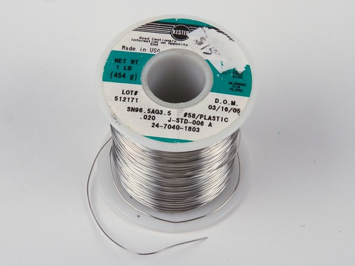
So, our spool of lead-free solder pictured above, with date of manufacture 3/16/05 expired five years ago in 2008.  Presumably one reason for a stated expiration date is that the flux becomes less active over time as it interacts with the solder metal.

But in our personal experience, this kind of solder seems to generally work just fine, even many years past its nominal shelf life.
Solder 3

Many others seem to have had a similar experience with solder wire.

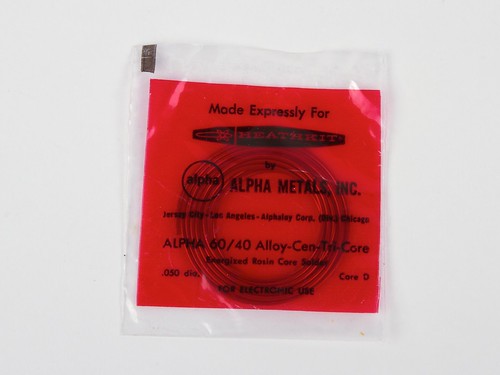
When we wrote about assembling a vintage Heathkit, we mentioned that it came with solder.  It actually came with two little packets of solder, specifically 60/40 rosin-core, cheerfully labeled “Made Expressly For Heathkit by Alpha Metals, Inc.”

Seeing as (1) the kit and solder date back nearly 40 years, (2) Alpha Metals also uses the three-year figure for shelf life, and (3) we already had a fresh, open spool of Alpha Metals 60/40 rosin-core solder in the lab, we opted to use the fresh spool and save the vintage solder packets for a rainy day.  Were we wrong to do so?   Certainly, some of our readers thought so:

Solder shelf life? Are you sure about that? Solder paste has a shelf life but I’ve never heard of a shelf life for a real coil of 60/40 rosin core solder. I’ve used some pretty old stuff myself, a quick Google search for solder shelf life found me a discussion where a guy is talking about using solder from the 60s with no problem on the first click!

So what has your experience been? Have you used “old” solder, and if so, how well did it work?

Surface Mount LEDs on a Through-hole PCB

Peggy 2le Surface Mount

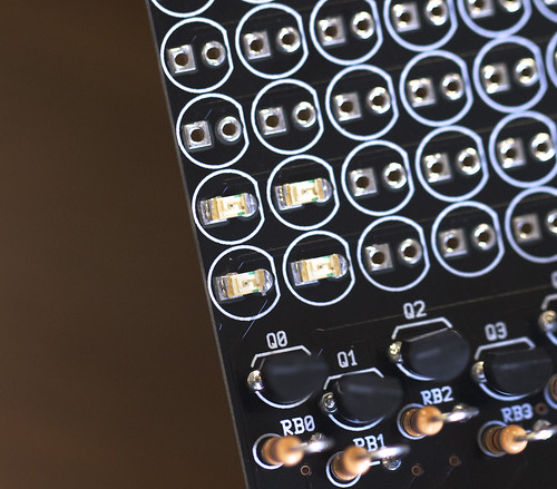
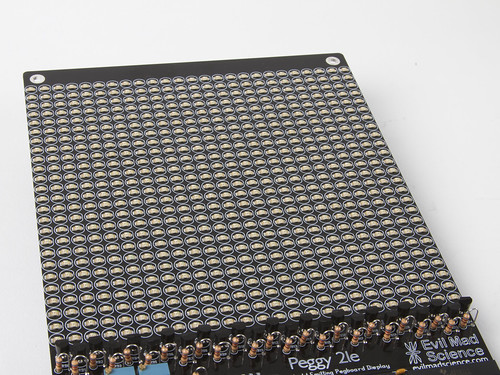
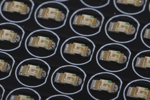
Peter T. recently stopped by our shop with his Peggy 2LE and showed us his incredibly cool hack. He had noticed that the 0.1″ pin spacing for a standard through-hole LED is just about perfect to accommodate LEDs in a 1206 surface mount package.

Peggy 2le Surface Mount

Once he had finished populating all the LED locations, he brought it by again. He used an alignment jig he had made to keep everything in straight rows while soldering.

Peggy 2le Surface Mount

The surface mount LEDs look great on the grid designed for T-1 3/4!

Peggy 2le Surface Mount

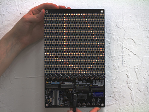
We plugged it in so we could see his pretty orange LEDs in action. Thanks to Peter for bringing it by and letting us take pictures!

Lightning Necklace

lightning_lolnecklace_11

Erin “RobotGrrl” recently posted about a wearables project:

Here was a quick project that I created in time for C2MTL. It’s a simple, blinky, 3D printed, wearable electronic. We wanted to wear something that would be interesting and a conversation starter.

lightning_lolnecklace_3


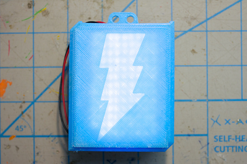
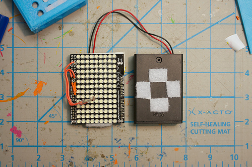
She used a LOL Shield on top of a Diavolino in a 3D printed case with a translucent lightning bolt. It was a success:

I wonder if all wearable electronic projects are like this- if people come up to you just because it’s something different and want to know more. Perhaps more world-wide friendliness & curiosity could be an unexpected result from wearable electronics! So, it worked and we were able to get people to talk to us. I extremely recommend this to other shy/not-exactly-social people.

Alpha Clock Five: Introducing the Blue Edition!

Introducing our newest open source hardware kit: The Blue Edition of Alpha Clock Five.

Alpha Clock Five Red  Alpha Clock Five White

Alpha Clock Five is our flagship clock kit, which thus far has been available only in a Red Edition and in a White Edition. Whichever color you happen to like, it is a full-featured, beautiful, and extraordinarily easy-to-read desk clock based around oversized 2.3″ alphanumeric LED displays. It’s designed to work equally well as a bedside alarm clock and as a computer-controlled alphanumeric data display device.

We’ve already written extensively about the core design of Alpha Clock Five. We’ve also written about the modes and features added in version 2.0 of our Arduino-compatible firmware (such as date display and daisy chained scrolling text), and about the hardware changes necessary to support the White Edition of the kit. Fortunately, the changes that we made in order to support the White Edition also allow us to support the use of blue LEDs, just as easily. And so— by popular request —we now present the Blue Edition.


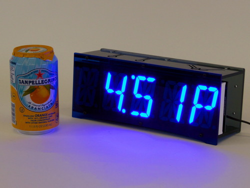
Here, the Blue Edition is shown with a soda can for scale. These LEDs are big and bright, and cast a heavy glow on the soda can and tabletop. (The usual caveats about the difficulty of photographing LEDs apply: A camera cannot capture the apparent intensity of pure blue LEDs in the same way that your eyes can.)


As with the other Alpha Clock Five kits, the control buttons are cut as flexures into the top of the laser-cut acrylic case, that can bend down to contact right-angle tactile button switches at the top edge of the circuit board. The top and bottom sides of the case are made of black acrylic, and the rear panel is made from smoke-gray acrylic.

For the Blue Edition, the front face of the case is made of deep blue transparent acrylic, which helps to increase display contrast, especially in brightly lit office environments.

Without the top and back panels, you can see the electronics within: the AVR microcontroller, LED driver chips, transistors, Chronodot RTC module and the other parts that make it all work.


The Blue Edition of Alpha Clock Five is available now at the Evil Mad Scientist shop.

Senko [Flash]

Tatsu Iida, a member of oxoxo [zero by zero] wrote in to tell us about the interactive LED installation entitled Senko [Flash] which they showed at the Tokushima LED Art Festival in April.

senko-body

They used a Peggy 2 to drive a field full of LED illuminated spheres, along with IR sensors to detect visitors entering the array. Each new person would trigger a new sphere to light up and move through the field.

?? [Senko] - Tokushima LED Art Festival

This is the largest installation we’ve ever seen based on the Peggy 2.

?? [Senko] - Tokushima LED Art Festival

Thanks for sharing your incredible project with us!

Links to many more Peggy 2 projects are on the wiki.

The 2013 Bay Area Maker Faire in Pictures

MFBA 2013 350

The 2013 Bay Area Maker Faire is a wrap— and it was amazing.  And we took pictures. We’ve uploaded 362 photos from maker faire right here for your browsing pleasure.   But first, a little preview.


MFBA 2013 322

Kids play with giant cardboard robot arms at the Giant Cardboard Robots booth. As they say, “The revolution will be corrugated.”

MFBA 2013 113

Glo-Puter Zero, by Alan Yates, with its phosphor-based memory. Truly a highlight of the show.


MFBA 2013 120

Lenore shares a nerdy moment with Akiba from Freaklabs.

MFBA 2013 83

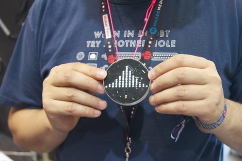
An unusual LED badge, from the Bay Lights project.

MFBA 2013 93

The Western Pyrotechnics Association is a club for people that make their own fireworks.  It’s incredible to see the complexity and artistry of the fireworks and the tooling that makes them.

MFBA 2013 305

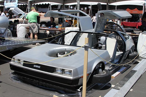
A beautiful hovercraft, designed to look like a flying DeLorean; you can see video of it on the project site.

MFBA 2013 188

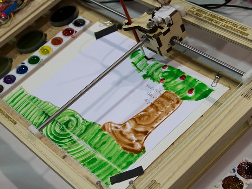
Back at our booth, the WaterColorBot was a constant hit.  Above, Sylvia shows visitors how to sketch with it in real time.

MFBA 2013 187MFBA 2013 189

An unexpected application: Our friend Bilal Ghalib stopped by and enlisted the WaterColorBot to help him make a birthday card for another friend.


MFBA 2013 273

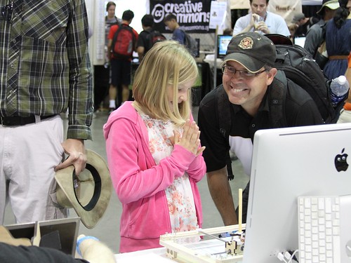
And one of our favorite moments of Maker Faire: a young visitor, tickled pink as she tries out the WaterColorBot, watching it paint a drawing that she had just sketched.


MFBA 2013 262

A bicycle-powered cardboard walking rhino, by Kinetic Creatures, makers of walking cardboard robot kits, with Theo Jansen inspired walking mechanisms.


MFBA 2013 324

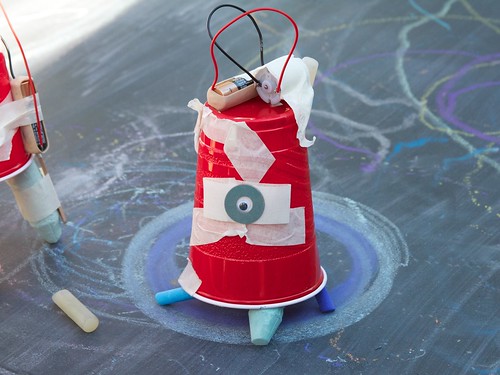
Some of the creations are simpler, like this sidewalk-chalk wielding vibrobot, spinning on a tabletop chalkboard at the Exploratorium booth.


MFBA 2013 175

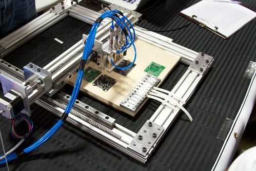
Some of the creations are more technical, like the OpenPNP project to create open source pick and place machines for electronics assembly.  We’re excited by where this is headed, along with a few related projects.


MFBA 2013 345

And of course, there’s no shortage of LED goodness.

Please click right here for the rest of our 2013 Bay Area Maker Faire photo album.


RoboGames 2013 Medals

Robogames_2013 35

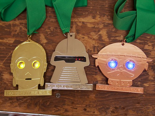
We helped build the gold, silver, and bronze medals for this year’s RoboGames competition, which finished up yesterday in San Mateo, California.

Read on for a bit about how we designed and built the electronics for, and assembled these pretty-darned neat medals.  It’s a story involving LEDs, some remarkable adhesives, and a how to operate a small-scale surface mount production.

Continue reading RoboGames 2013 Medals