Category Archives: Electronics

From the mailbag: flickering LEDs in series

We recently got a question about our flickering LEDs:

I’m wondering if it’s possible to wire these in series?

It’s a good (and not entirely uncommon) question, and the short answer is: “Yes, but not with each other.”

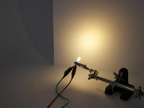
These LEDs have a little chip inside that turns them on and off in a flickering pattern. You can see it in the photo of the flat-topped white LED above. On the upper pad is the yellowish phosphor over the LED die. On the lower pad is the chip that turns the LED on and off.

If you put two of these in series, the first one turns the next one on and off repeatedly, interrupting the second chip and preventing it from executing its flickering pattern. The result is that you get momentary blinking, but not the nice flickering pattern.  (So yes, both would in fact light up; they just don’t behave how you might hope that they would.)

So how can you hook up a bunch of flickering LEDs together? If you want each LED to flicker separately, you can hook them up in parallel. But there is a way to use these in series with other LEDs. We can even use this to combine multiple LED colors to create some fantastic LED “flames” that would be great for stage props or putting inside pumpkins.
Continue reading From the mailbag: flickering LEDs in series

The Art Controller

Art Controller

Today we’re releasing a new open source kit: A stand-alone, microcontroller-driven relay module called the Art Controller.

The Art Controller project was originally suggested by our friends (and Maker Faire regulars), San Francisco Bay Area kinetic artists Christopher T. Palmer and Nemo Gould.  Amongst other things that they build are amazing mechanical sculptures that need to run for a little while after a visitor presses a button or inserts a coin into the slot.

The long-established solution for driving electronic artwork (along with many similar endeavors) is to use a timer relay module; a little stand-alone board with a relay controlled by a timer.  There are several types of these: fancy programmable modules, bulletproof industrial types, and simple low-cost boards with a 555 timer and a pot that you turn to adjust the delay.  As we understand it, Christopher and Nemo go through the latter type like jellybeans.  But, what they realized that they really wanted was something just like that, except that you could reprogram it if you wanted to.

Art Controller

Hence the Art Controller.   It’s a low cost stand-alone relay module, with an on-board AVR microcontroller, an ATtiny2313, that manages the timing and I/O.

It can be used as a replacement for one of those basic 555-based relay boards, but it’s considerably more flexible in terms of timing range and functionality:

  • The timing is adjusted with an 8-position DIP switch, rather than a knob.  This cuts down on guess-and-check, but also gives a huge range. With those 8 little switches, you can select times from 1 second to 31 hours. (The ranges are 1-31 seconds, minutes, or hours, plus a few intermediate ranges.)
  • It can work as a one-shot timer or a continuously repeating timer.
  • There’s an option to trigger automatically upon turn-on (reset).
  • There’s a separate cancel input, so you can build a “STOP” button.
  • There’s an option to cancel a trigger if you push the “START” button a second time.

It comes preprogrammed, and all of those adjustments can be done with switches and wiring— handy if solder is your favorite programming language —so no computer or programming are actually required to get that far.

But, when that’s not enough, the on-board microcontroller can be reprogrammed in situ (using the board’s AVR ISP programming header) to handle the most specialized applications, potentially taking advantage of up to 16 free digital I/O pins.

And that’s pretty neat. 

Art Controller

Beyond the obvious applications in DIY projects, automation, and controlling art projects, we think that this is also going to be a fantastic relay board for education. It starts out as a (well-designed) simple function timer relay board, but can optionally transition to a full-on microcontroller development board when you’re ready for it.

So that’s the Art Controller in a nutshell: a versatile, easy to use, low-cost relay board that you can reprogram if you want to.

There’s plenty more detail on our product page: The Art Controller at Evil Mad Science.

And, special thanks to Christopher T. Palmer and Nemo Gould for a great project idea!


This post is included in our Halloween Project Archive, where you can find ideas for props, decor, and more.

Mailbag: Hacking a Mega-Peggy

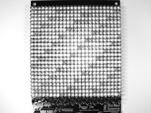
grayscale

Tony writes in with a question about hacking our DIY LED matrix kits:

“I’m building a Peggy 2LE. I have completed the wiring with the exception of the LEDs. I have constructed an external frame which has 600 mounting points for my LEDs using a Matrix design of wires crossing every 3 inches. Since the Peggy 2LE has 625 LEDs I need to know how I can drive the 30 anode connections and 20 cathode connections to the wiring them to the Peggy 2. Or am I going to have to wire each LED to the PCB of the Peggy + and – LED locations?”

And, that’s actually an interesting topic.  We’ve written before (here and here) about some giant-scale variations and modifications to our Peggy 2 and Peggy 2LE LED matrix kits, but we haven’t really addressed how one might go about building it.

First off, since you asked— and though we recommend against it —it is indeed possible to build an off-board LED matrix by simply running individual running wires from every LED location on the Peggy circuit board to every LED.  There are 625 LEDs in a 25 × 25 grid, and if each has two wires… that turns out to be quite a few wires.

MakerFaire2011 - 144

While *ahem* labor intensive, this method does work. We know this partly because several people have actually done it.  The “rats nest” of thin, red-lacquered magnet wire shown above is one example, and the Peggy shown here is another victim example of this method.

Fortunately, very fortunately, there are easier ways: think 50 wires, rather than 1250. And, there are a few other clever tricks that you might want to consider when changing the size of the matrix.  For example, it’s possible to use the Peggy 2LE to drive an off-board LED matrix of size up to 25 × 32 without adding any other extra hardware.

Continue reading Mailbag: Hacking a Mega-Peggy

Basics: Picking Resistors for LEDs

5 mm warm white diffused LED

So… you just want to light up an LED. What resistor should you use?

Maybe you know the answer, or maybe everyone already assumes that you should know how to get to the answer.  And in any case, it’s a question that tends to generate more questions before you actually can get an answer: What kind of LED are you using? What power supply? Battery? Plug-in? Part of a larger circuit? Series? Parallel?

Playing with LEDs is supposed to be fun, and figuring out the answers to these questions is actually part of the fun.  There’s a simple formula that you use for figuring it out, Ohm’s Law. That formula is V = I × R, where V is the voltage, I is the current, and R is the resistance. But how do you know what numbers to plug into that formula to get out the right resistor value?

Continue reading Basics: Picking Resistors for LEDs

Prefabricated Octolively Modules

Octolively Modules

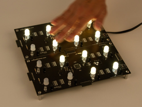
Last year we released Octolively, an open source interactive LED kit, designed to respond in gentle and complex ways to stimulus provided by human interaction.

While Octolively has been a success (and a lot of fun), thus far it has only been available as a soldering kit. Today, we’re pleased to supplement those with a new version: prefabricated Octolively modules, all built-up and ready-to-use, so you can jump right in and start playing with the LEDs.


Octolively Modules

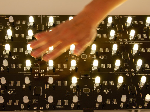
Like the soldering kit version, each “prefab” Octolively module is 4 × 8 inches (10.16 × 20.32 cm) in size, and features eight huge (10 mm) ultrabright LEDs, spaced along a two-inch grid.  And, for every LED, there is an independent infrared proximity sensor pair, configured to act as a reflective motion sensor.
Octolively Modules

The most obvious change from the soldering kit version of Octolively is that the topside components take up a lot less space. All of the resistors, capacitors, and the microcontroller have been replaced by their surface mount equivalents.


Octolively Modules

However, this not really a “surface mount” circuit board, it’s more accurately a “mixed technology” board.   Some of the components— in particular many “optoelectronic” components, like our visible and infrared LEDs —just don’t have great surface mount versions.  For example, when we’ve tried building motion sensors circuits with SMT infrared LEDs (even the pricier types that have itty-bitty lenses) we found that they just didn’t project enough IR light to be effective. Similarly, we’ve found that visible surface mount LEDs tend to be perceived as dim, even when a huge amount of light is being emitted, because the light usually goes into a very wide angle.


Octolively Modules

The microcontroller is an Atmel ATmega164A, in the 44-pin TQFP package.  (And in case you’re wondering, yes that’s exactly as redundant as “ATM machine.” )

Those white gumdrop-looking things are (as before) the big 10 mm LEDs, but they certainly seem even bigger sitting next to that chip.


Octolively Modules

Ready-to-use Octolively modules are available now at Evil Mad Science.

Additional details— including the datasheet and documentation links —are available on the product page.

Mystery components!

MysteryComponent1
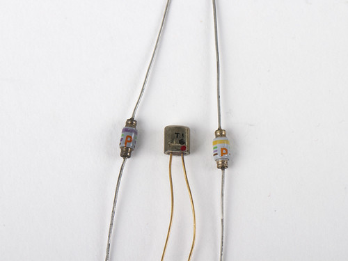
While picking out interesting vintage diodes at the electronics flea market, we came across a couple of components— possibly also diodes because of where we found them —of types that we have never seen before.  And we can’t resist a good mystery.


MysteryComponent4

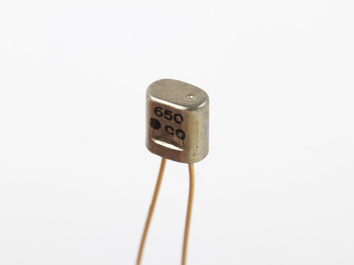
First, there’s this little two legged can, marked with 650, a black dot, and CO on one side. The other side (as you can see in the photo above this one), is marked T 1 and has black and red dots.


Secondly, a couple of things that look kind of like resistors:
MysteryComponent6

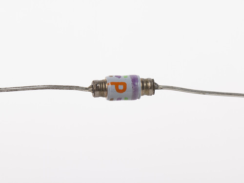
They are very small, only about the size of 1/4 W resistors.  They are marked with a red capitol letter “P” and a set of four colored stripes. The “P” marking interrupts the three narrower bands in both cases.

MysteryComponent8
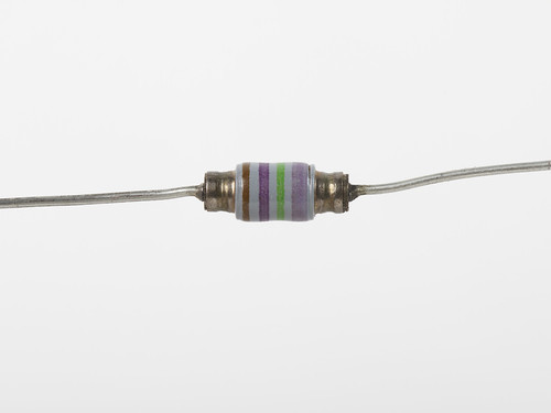
Here’s a good look at the color bands: brown, violet, green, and then a broad yellow.  (We could be reading this wrong; is the broad stripe supposed to be read first?)

MysteryComponent7
This one has brown, violet, green, and then broad violet.

So, what are they?  We don’t actually know, but if you do, or if you have a good guess, we’d love to hear it!

Interesting Diodes from the Electronics Flea Market

Diodes from the eFlea

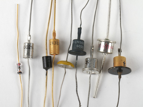
We have written before about the the Silicon Valley Electronics Flea Market, one of our favorite places to go treasure hunting. At this weekend’s flea, we came across a cache of beautiful old diodes, including some in rather unusual packages.

Continue reading Interesting Diodes from the Electronics Flea Market

Basics: Blink an LED with an AVR

AVR Blink Blog Post

Getting an AVR to blink might seem like an incredibly difficult task compared to the usual Arduino blink, but it really isn’t! In this post we will be uploading a basic blink example to an ATtiny2313. This is perfect for projects where using an Arduino would be over the top. So let’s get started!

Continue reading Basics: Blink an LED with an AVR