Category Archives: Electronics

Basics: Open Collector Outputs

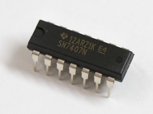
SN7407N

One of the joys of working with basic digital electronics– and logic gate ICs in particular –is that it almost works like building with a set of Lego blocks: One output goes here, which connects to the next input here, and so forth until it does what you wanted.

If you’ve played with chips like these, you’ve probably also come across chips with “open collector” outputs. And if not, they’re worth knowing about. Open-collector outputs form the basis of a number of clever tricks for level-shifting and interfacing between different types of logic, and from logic to other types of electronic circuits.

In what follows, we’ll work with the SN7407N, which is one of the most basic ICs with open-collector outputs. We’ll discuss what it means to have “open collector” outputs, and show some of the different ways that they are used. Continue reading Basics: Open Collector Outputs

Basics: Power dissipation and electronic components

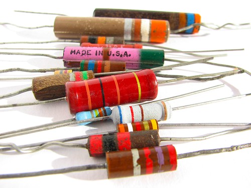
Lovely Resistors


An ever-present challenge in electronic circuit design is selecting suitable components that not only perform their intended task but also will survive under foreseeable operating conditions. A big part of that process is making sure that your components will stay within their safe operating limits in terms of current, voltage, and power. Of those three, the “power” portion is often the most difficult (for both newcomers and experts) because the safe operating area can depend so strongly on the particulars of the situation.

In what follows, we’ll introduce some of the basic concepts of power dissipation in electronic components, with an eye towards understanding how to select components for simple circuits with power limitations in mind. Continue reading Basics: Power dissipation and electronic components

Basics: Introduction to Zener Diodes

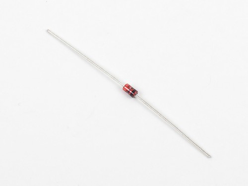
zener2

Zener diodes are a special type of semiconductor diode– devices that allow current to flow in one direction only –that also allow current to flow in the opposite direction, but only when exposed to enough voltage. And while that sounds a bit esoteric, they’re actually among the handiest components ever to cross an engineer’s bench, providing great solutions to a number of common needs in circuit design.

In what follows, we’ll show you how (and when) to use a Zener, for applications including simple reference voltages, clamping signals to specific voltage ranges, and easing the load on a voltage regulator. Continue reading Basics: Introduction to Zener Diodes

Evil Mad Science Kits on Make: Live!

The most recent episode of Make: Live was a special episode on kits to celebrate the upcoming release of the Make: Special Issue, The Ultimate Kit Guide. Our very own Octolively and Meggy Jr RGB kits were both featured on the show. The electronic kits clip is embedded above, or you can watch the full video and the rest of the clips, including siege & ballistic kits and crafty kits on the Ultimate Kit Episode post over at Make.

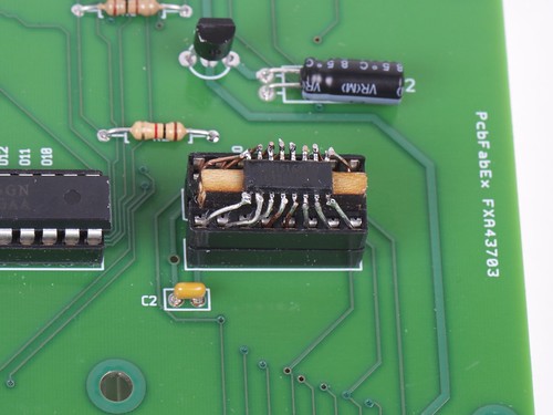
Basic kludges: 5 minute SOIC-DIP adapter

Socket Adapter - 5

So, you’re almost done building the new circuit board when suddenly…

Socket Adapter - 7

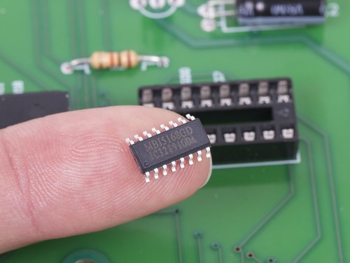
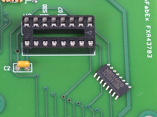
Doh! We’ve got the right chip handy, but only in the wrong package!

Socket Adapter - 6

No siree, that chip will not fit in our socket. :(

Socket Adapter - 2

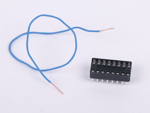
Fortunately, we’ve got tools: some thin copper wire, a spare DIP socket, and a few minutes of time. So, even without a readymade SOIC-to-DIP adapter, we’re still good to go.

Socket Adapter - 4

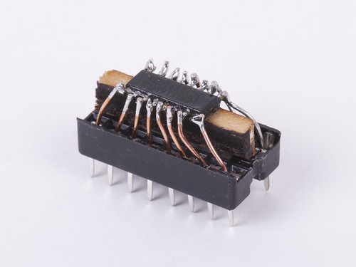
It’s helpful to raise the little chip up a bit with a wood or plastic shim, and then to fix it in place with hot or super glue. Strip the insulation off of the wire, and cut into small sections. Starting at the center of the chip, insert one end of each little wire into the socket and solder the other end to the matching pin of the IC. Trim the leads just above the chip.

Socket Adapter - 8

And (poof!) it fits in the circuit board after all.

Beautiful? Heck no. (More like slimy but satisfying.) But finding a way to get your circuit board to light up without a few more days for the “right” chip to show up can be a wonderful thing indeed.

Halloween Projects from Evil Mad Scientist Laboratories

The Great Evil Mad Scientist Laboratories Halloween Project Archive!

Halloween is one of our favorite holidays, and our collection of Halloween projects continues to grow. Every fall we update it to include our latest projects for the season. In the list that follows, we’ve organized dozens of our Halloween projects into categories: costumes, pumpkins, decor and food.

Last updated: 10/2019.

Continue reading Halloween Projects from Evil Mad Scientist Laboratories

Improving open source hardware: Visual diffs

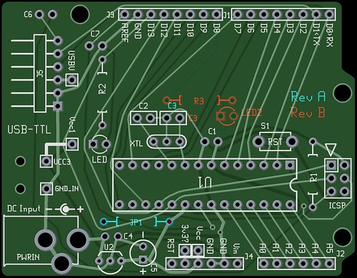
pcbdiff

As the open source hardware movement matures, it’s worth taking a moment to consider the issue of version control.

Collaborative software projects make heavy use of version control– tools like Subversion and Git, and project hosting sites like SourceForge, GitHub, and Google Code –to organize and manage the contributions of many developers to a project. But as we begin to consider open source hardware, can we use these same tools and sites for effective collaboration on hardware projects?

The short answer is, “yes”– after all, people are already doing it. But the reality is that we could do much, much better. Some people think that we do need a separate “SourceForge for hardware.” That’s hard to say. But it is the case– perhaps against conventional wisdom –that existing tools can be used, today, for meaningful hardware version control.

It’s certainly possible to take any old binary file (say from a CAD program), and store it in a version control system. This is, in fact, how many of today’s open source hardware projects are managed. However, a “diff” (direct file comparison) to see what’s changed between two versions of a given file is all but meaningless.

For design files in plain-text (“ascii”) file formats, such as Inkscape‘s SVG or KiCad‘s .brd, a diff is possible and is in principle meaningful, but it is usually all but useless in practice, because CAD is a graphical sport, and we need to treat it like graphics.

An example: Suppose that you found the following snippet in the difference between two SVG files:

 <path
       sodipodi:type="arc"
       style="fill:#ff00ff;fill-opacity:1;stroke:#ffa6a6;stroke-width:0.18000001;stroke-linecap:round;stroke-linejoin:round;stroke-miterlimit:4;stroke-opacity:1;stroke-dasharray:none;stroke-dashoffset:0"
       id="path2816"
       sodipodi:cx="237.14285"
       sodipodi:cy="328.07648"
       sodipodi:rx="160"
       sodipodi:ry="84.285713"
       d="m 397.14285,328.07648 a 160,84.285713 0 1 1 -319.999997,0 160,84.285713 0 1 1 319.999997,0 z" />

You probably wouldn’t recognize that (at least not quickly) as a big magenta ellipse. While it’s perfectly legible as source code, a diff result like this would be all but useless in practice.

The obvious solution, is to add in some visual diffs in order to make sense of changes between design files. On the bright side, making these is remarkably straightforward, and– with a little bit of effort –practically supported by existing version control systems.

In what follows, we’ll walk through some examples of visual diffs– with bitmaps and PDF files –and discuss what you can do to help make version control work better for CAD files, and to make CAD files better for version control.

Continue reading Improving open source hardware: Visual diffs