Category Archives: Electronics

Mega Menorah 9000!

MM9k

MM9k  MM9k

Introducing our newest Hanukkah menorah kit: Mega Menorah 9000!

This is a great new easy soldering kit to make a handsome and decently-sized menorah. Once built, it stands just over 6 inches (15 cm) tall, and is 7.5 inches (19 cm) wide.

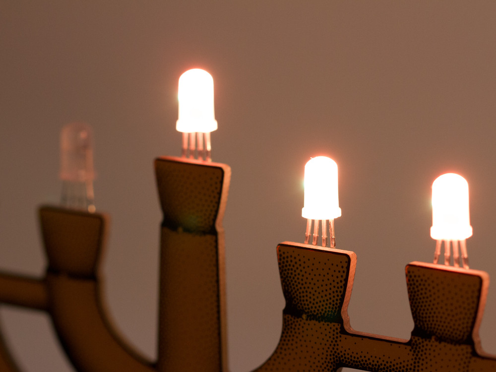
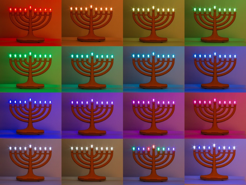
It’s USB powered, USB programmable with a built-in interface based on the Adafruit Trinket, and features 9 discrete RGB LED “pixels” that can produce all kinds of bright colors. Flickery flame effects built in too, of course.

MM9k

One of the cool things about this kit is that it has a unique “Trompe-l’œil” circuit board design that gives some illusion of a rounded 3D surface. As you can see above, it’s actually flat as a board.

To make it, we started with a 3D CAD model of what we wanted the circuit board to look like. The outer contours of the model became the outline of the circuit board. We then rendered the CAD model, and used our StippleGen 2 software to convert the resulting image into a vector stipple drawing— one that could eventually be converted into the artwork for the circuit board. All together it’s over 9000 stippled dots of black silkscreen! (To be more specific, there are roughly 17,000 dots on each side.)

MM9k FAQ: OK, but isn’t the name “Mega Menorah 9000” perhaps just slightly on the excessive side?
Yes, we must (grudgingly) admit that it is. It just slipped out when we were trying to come up with a working title for the project — a name that meant “better than deluxe” so as to distinguish this model from our old favorite Deluxe LED Menorah Kits.
Alas, it was funny. And so it stuck. And now, it’s too late.

MM9k  MM9k

There are two circuit boards in the kit. The “top” PCB is shaped like a menorah and the components (mainly just the nine WS2812-style LEDs) are for the most part hidden on the back side.

The base circuit board has rubber feet, the control buttons (color, night, reset), an ATtiny85 AVR microcontroller, USB power/programming jack, and a programming indicator LED. The circuit is actually an implementation of the Adafruit Trinket, which allows for reprogramming the microcontroller without requiring any hardware other than a regular USB cable.

MM9k FAQ: Why is there a binder clip there?
It’s an assembly jig that helps to align the parts in place so that it’s easy to build and looks neat. We’ll write more about it later.

MM9k

And, wow does this thing do colors! The nine WS2812-style individually addressable RGB LEDs in 5 mm packages, look reminiscent of candle flames, but can be tuned to just about any color in the rainbow. From a control standpoint, it’s awfully nice that they’re managed by just a single pin of the microcontroller, and have the built-in ICs to handle colors and dimming.

Mega Menorah 9000 begins shipping this week.

The DIYIC Protoboard

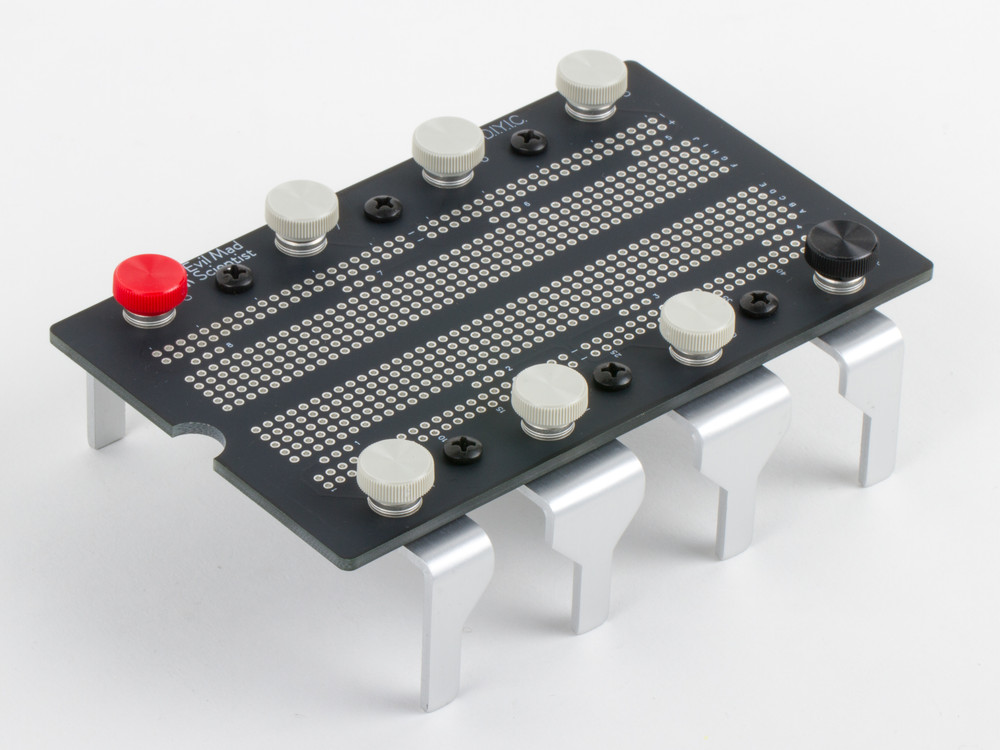
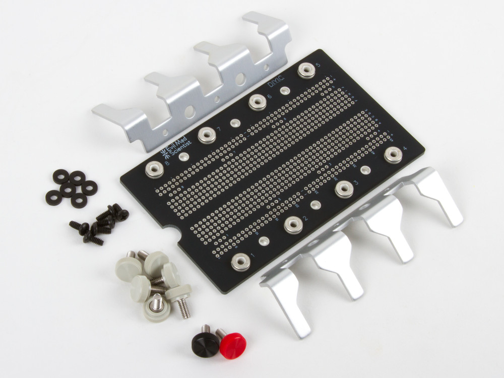
Introducing our new kit, DIYIC, which stands for “Do-It-Yourself Integrated Circuit!” This breadboard-style solderable proto board is shaped like a giant integrated circuit. It’s a freeform complement to our 555 and 741 “dis-integrated circuit” kits. Make your own custom 8-pin integrated circuit, use it as a giant connectorized breakout board for smaller components, or however you see fit.

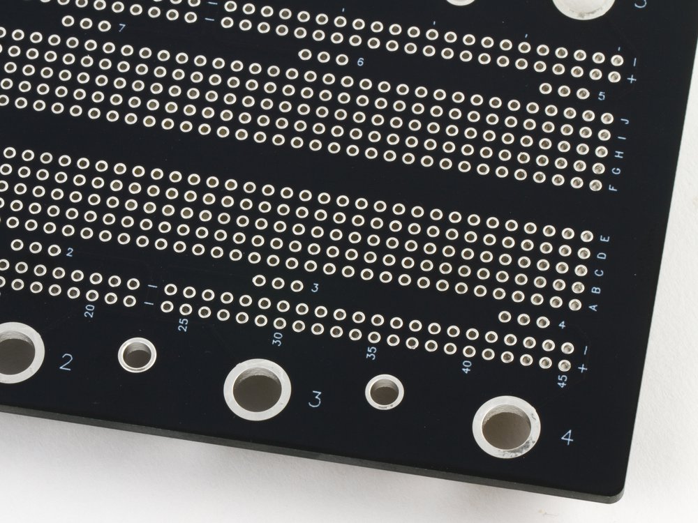
Fine labeling

The matte-black circuit board is extra thick and has subtle white markings including an alphanumeric grid and pin number labels.

reverse side of PCB

The wiring pattern — that of classic breadboards — is easy to see by looking at the exposed traces on bottom of the board. Connections to the 8 terminal posts are through the three-position strips on the PCB; each is labeled with the corresponding pin number.

The DIYIC is available either as a bare circuit board or in a full kit, complete with the “Integrated Circuit Leg” stand and 8 color coded thumbscrew terminal posts.

Ostrich EggBot 2.0

Ostrich EggBot
Ostrich EggBot

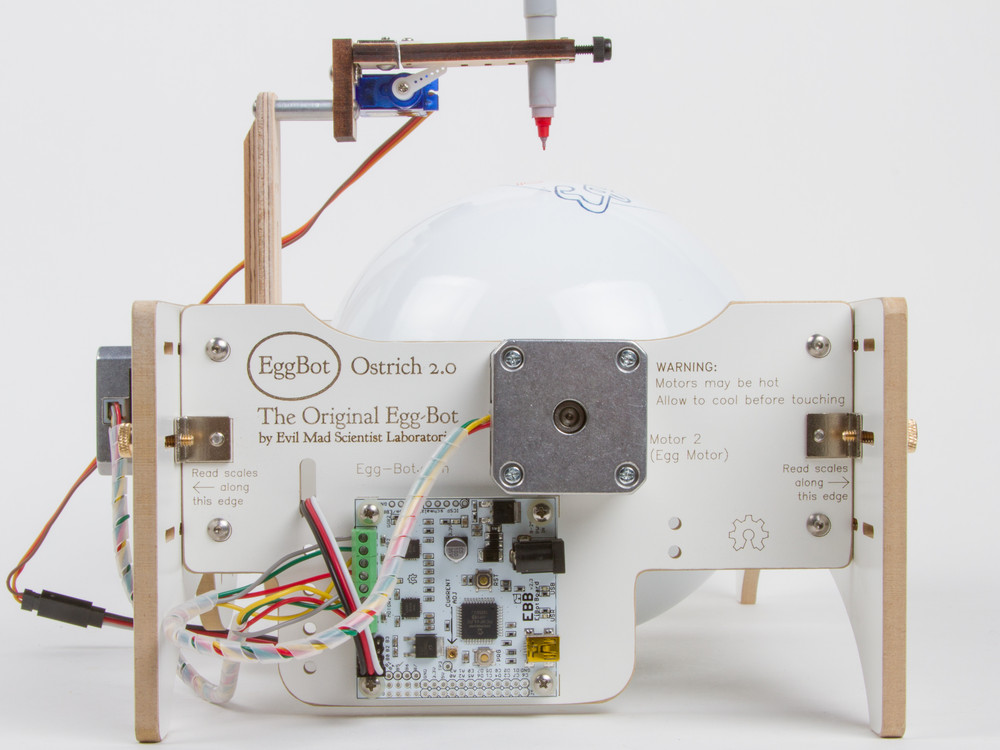
We’ve just released version 2.0 of our Ostrich EggBot kit!  This is the giant size EggBot. Like the smaller models, it’s a machine capable of drawing on the surface of all kinds of spherical and egg-shaped objects up to 6.25 inches (15 cm) in diameter, including large ostrich eggs.

This chassis of the new version is CNC machined from melamine-faced MDF, and laser engraved with markings and calibration scales. (The previous version was made of plywood; you can read about it here.) We’ve also updated the graphics, and rolled in a number of subtle improvements based on user suggestions and our own extensive experience with the machine and other members of the EggBot family.

Ostrich EggBot Ostrich EggBot

With a relatively large chicken egg chucked into the holders, you can get a better sense of scale. (An ostrich egg is a terrible object to suggest a sense of size!)

The tailstock (the sliding portion of the right hand side) has been slightly redesigned for higher stiffness and better ease of use. The bulk of the stiffness in the directions that we care about (that is, in the directions where the chassis material is not strong) derives from the steel angle brackets, and the new tailstock helps to reinforce that for better overall rigidity.

Ostrich EggBot

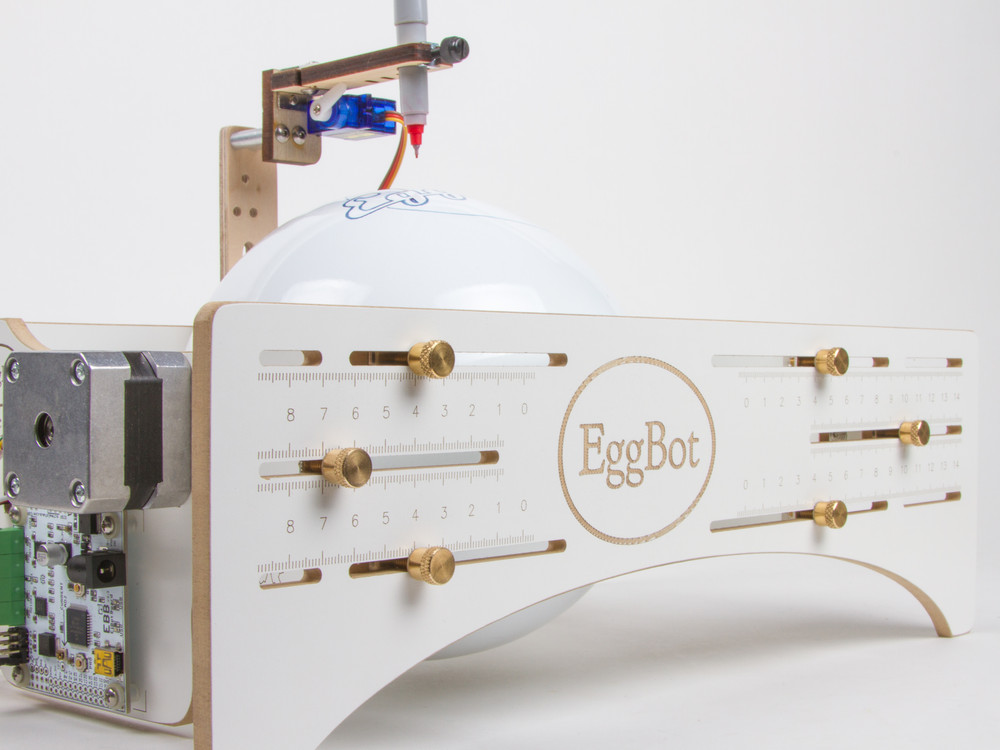
One of the best things about the new chassis material is that it laser engraves particularly well, giving high-contrast, highly readable adjustment scales on the sides. And that makes it all easier to use in practice. All considered, this has turned out to be quite a nice little upgrade.

Solderless Flickery Flame

We’ve talked previously about making simple LED pumpkins with candle flicker LEDs. Lately we’ve been playing with making better looking flames by using multiple independent flickering LEDs with different colors and lens styles. It makes a spectacular difference: it goes from something that looks like, well, a flickering LED to something that really looks like there might be a flame in there.

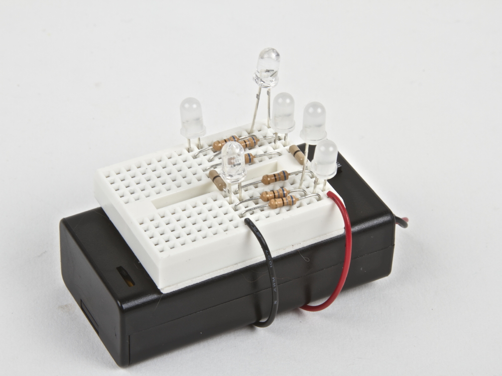
The end result is pretty neat: A compact battery powered “flameless flame” that looks great in a pumpkin, luminaria, or as a stage prop. The interplay of the different LED types and colors gives an ever-changing and shifting flame display.

Other than the candle flickering LEDs, the parts are commonly available. We’ve also bundled them together in the Solderless Flickery Flame Kit.

Components:

  • Battery Holder (2×AA with switch)
  • Mini-breadboard
  • 6 × candle flicker LEDs (2 red diffused, 2 yellow diffused, and 2 yellow clear lens)
  • 6 × 68 ohm resistor
  • 2 × wire jumper
  • White paper bag (optional)

Also needed:

  • 2 × AA Batteries (not optional)
  • Wire clippers, cutting pliers, or “beater” scissors (optional)

Hook up the battery holder to the breadboard several rows apart to give enough room to install the resistors and LEDs. Optional: peel off the backing on breadboard and adhere it to the battery holder. Connect each LED with its own 68 ohm resistor. (Use the “in parallel” method from this article.) The extra jumpers are included to help bridge across the center gap in the breadboard.

Trimming the resistor leads will keep the breadboard tidy, and help prevent short circuits. Trimming the LED leads to varying heights will help distribute the light in different ways.

The white paper bag included with the kit can be used for creating a traditional luminaria or for making a ghostly halloween decoration.


You can find more Halloween decor projects in our Halloween Project Archive.

Fixing on the fly at Maker Faire

Maker Faire can be a pretty demanding environment for a project. Outdoor locations expose many projects to the weather, prototypes may have been unpacked and repacked by the TSA, and curious visitors may handle projects in new and unexpected ways. Or maybe ambitions were greater than preparation time, and the project just didn’t quite get finished before the fair opened. No matter what the reason, Maker Faire is a great place to see people in action fixing, troubleshooting, and finishing their projects. Below are some beautiful projects I caught in progress at Maker Faire New York.

Pick n place

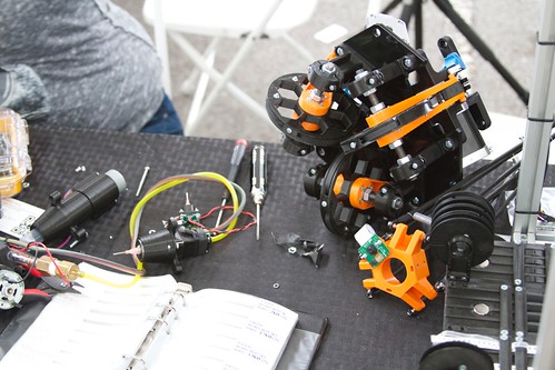
The FirePick Delta pick and place machine was a victim of the TSA, and arrived less functional than when it had been packed. The team was working on it valiantly, which also provided opportunities to get a closer look at many of the components.

Pick n place

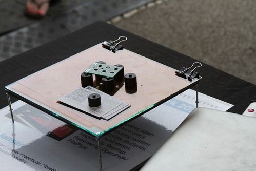
Components not in use were repurposed for holding down business cards in the breezy aisle of 3D village.

Fixing robotic soccer

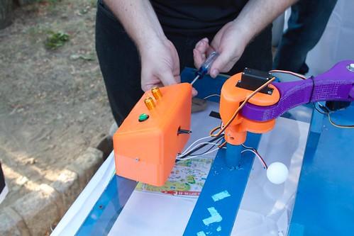
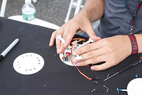
The maker of this robot arm soccer game was opening up one of the control boxes to check on a malfunctioning knob.

Robotic soccer (after repair)

He had no shortage of willing testers after the repair.

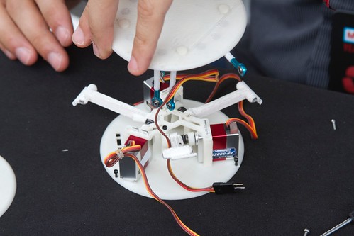
Tiny 3D printer under repair

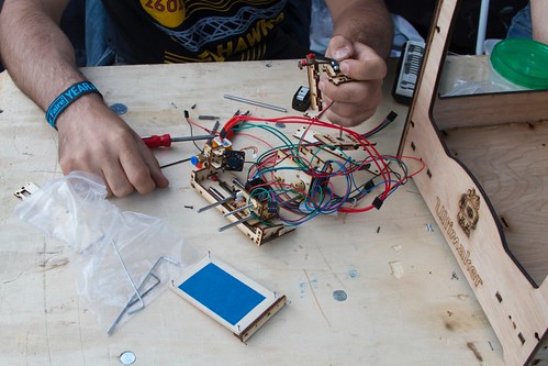
This half-scale 3D printer assembly was at least as charming in its disassembled state as it would have been all put together. It is great to see the components along with the kinds of tools that are used to assemble and repair projects like this one.

Gertie the jumping robot

Gertie the robot had seen quite a bit of action, first at the Bay Area Maker Faire and then in New York. Her actuators were apart and in the middle of repair when we came by.

Gertie the jumping robot

This let Alonso show us the mechanism and demonstrate how the internal frame worked to lean and make Gertie jump in different directions.

Maker Faire exhibitors are generous with sharing tools and materials with each other, and visitors are treated to what are typically hidden activities. No one whisks away a broken prototype to hide it out of sight. Instead, the guts are happily spilled out for everyone to see and learn from.

Soldering Tip Tinning with Sal Ammoniac


If you solder, you’ve likely come across an “untinned” tip at some point— that’s when the tip of your soldering iron loses its shine, and doesn’t easily wet to solder any more.

Once your tip gets this way, it doesn’t make nearly as good of a thermal contact to whatever you are trying to solder, and it simply doesn’t work well. Soldering can take 2-10 times as long, and that isn’t good for your circuit board, components, or mental health.

You can sometimes re-tin the tip by melting fresh solder onto it, but that can be challenging, because the whole problem is that the tip isn’t melting solder. It’s particularly hard to keep tips tinned with modern lead-free solder, because it needs to get even hotter to begin melting.  If you get to this point, you might think about even replacing the tip.

But before you throw that tip away, instead consider using one of the “old standard” solutions, which is to refurbish the tip with a tip-tinning compound. And we came across the most classic of them in one of the most unexpected locations.  Continue reading Soldering Tip Tinning with Sal Ammoniac

From the mailbag: Bulbdial Clock Kit

Bruce B. wrote in to say:

I recently bought one of your Bulbdial clock kits. I just wanted to send a quick note to say that your step-by-step guide was the BEST guide I have ever seen, for anything. I have assembled many an item in my years and instruction sets vary from useless to marginally worthwhile. The Bulbdial guide was amazing! You should publish a step-by-step guide on how to write step-by-step guides :)
Oh, and the clock is amazing as well!

The XL741 Discrete Operational Amplifier

Ever since we released our Three Fives discrete 555 timer kit last year, people have been asking us “When are you going to come out with a 741 op-amp?” It has taken us quite a while to get here, but the answer is… Today!

Our XL741 Discrete Operational Amplifier is a real, working op-amp that you can build yourself.  It’s a transistor-scale version of the original ?A741 integrated circuit, that incredibly versatile and popular analog workhorse. As with our 555 kit, you can probe inside to see the inner workings of the circuit as it works. And, like our 555, it comes with a beautiful anodized aluminum “IC legs” stand, so it even looks great when it isn’t plugged in.

The kit was designed and developed as a collaboration with Eric Schlaepfer, and is a direct adaptation of the equivalent schematic from the original Fairchild ?A741 datasheet.

If you’ve ever used operational amplifiers, you’re probably familiar with the ?A741 (or colloquially, just “the 741”). Designed by Dave Fullagar and released by Fairchild in 1968, it’s the quintessential and most popular op-amp of all time. While newer op-amp designs easily outperform the ?A741 in just about every possible respect (speed, noise, voltage range, and so on), the 741 remains widely beloved and in active production by multiple manufacturers even today — over 45 years later.

And, if you haven’t used an op-amp, this a great way to learn. Op-amps are simple, wonderful building blocks for making analog computers. With op-amps, you can build circuits that can (for example) add, subtract, amplify, take logarithms, perform integration, or perform other operations on your signals. Or buffer and copy them, or cleanly convert current to or from voltage, and on and on and on.

A regular op-amp is an integrated circuit; a little black box. The XL741, on the other hand, is a big black box, with a heck of a lot of points where you can can probe inside, to see what’s going on, in real time. And that’s a unique opportunity.

The XL741 is a quick, easy to build soldering kit, with through-hole components, and not too many of them. (And, have you see our awesome resistor wallets?)

And, best of all, the XL741 is in stock, and begins shipping today. 

Visit our store page for links to the XL741 datasheet, assembly instructions, and additional documentation resources.