Ubergenius posted his Snap-O-Lantern built with a foam pumpkin:
Awe, it’s so… OMG!!! #evilmadscientist #battleforthebones


Ubergenius posted his Snap-O-Lantern built with a foam pumpkin:
Awe, it’s so… OMG!!! #evilmadscientist #battleforthebones
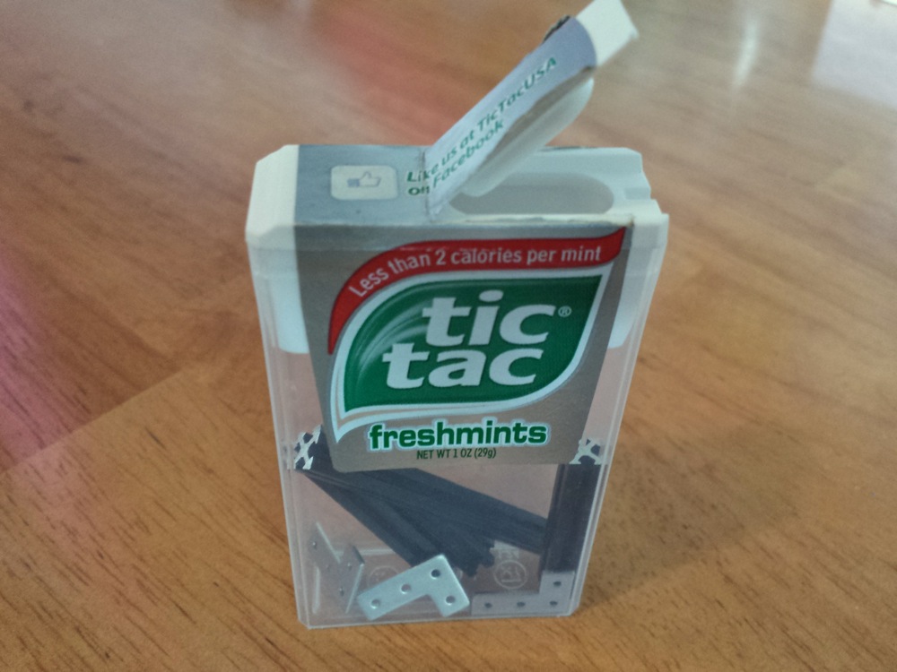
When we saw NanoBeam on Kickstarter, we had a hard time comprehending just how small it is. So we asked Hyrum if he could send us some pictures for a better sense of scale, and he obliged. Yes, it fits in a tic-tac box. After seeing just how teeny-tiny a 5 mm beam is (one quarter the cross sectional area of Maker Beam and one ninth of Open Beam), our next question was “What the heck?” So we asked what made him think of making such a tiny beam.
I just wanted some tiny beams to build a small robot. I looked all over the place but couldn’t find what I wanted. After some research, and talking to some extruding companies, I designed a beam that was so small it challenged all the rules of this manufacturing science. I made a few on my cnc mill before I commissioned the die, to be sure it was what I wanted.

How did you find a factory to work with?
I combed the web and talked to a lot of companies. I finally found one that focused on small extrusions. I saw the amazingly small and precise work they were doing for companies like Boeing and 3M and I knew I found the company I needed.
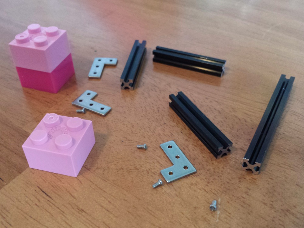
What kind of fasteners do you use for something this small?
I used the largest screw I could but they are still small. The size is M1.2; you will find these in some pairs of glasses. I’ve got 3 designs for the nuts, I am waiting on manufacturing samples for the last one before I decide for sure which I will use.
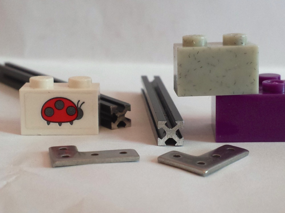
We asked what he thought NanoBeam would be useful for.
Immediately, I see this making a splash with small robots, quad copters and electronic enclosures. I also see it being great for diy wearables, scale models and crafts. I recently got feedback from a guy that wanted to use them as a frame, conductor and heat sink for an LED array. I can’t wait to see something like that. I’m going to get some stock without the black coating for this application.
We’re also very interested to see what people do with such a tiny extrusion! Thanks to Hyrum for answering our questions. You can find out more, and check out his designs (Open Source Hardware definition compliant) at the NanoBeam website and the Kickstarter campaign page.
We’ve talked previously about making simple LED pumpkins with candle flicker LEDs. Lately we’ve been playing with making better looking flames by using multiple independent flickering LEDs with different colors and lens styles. It makes a spectacular difference: it goes from something that looks like, well, a flickering LED to something that really looks like there might be a flame in there.

The end result is pretty neat: A compact battery powered “flameless flame” that looks great in a pumpkin, luminaria, or as a stage prop. The interplay of the different LED types and colors gives an ever-changing and shifting flame display.
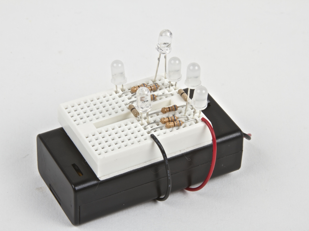
Other than the candle flickering LEDs, the parts are commonly available. We’ve also bundled them together in the Solderless Flickery Flame Kit.
Components:
Also needed:
Hook up the battery holder to the breadboard several rows apart to give enough room to install the resistors and LEDs. Optional: peel off the backing on breadboard and adhere it to the battery holder. Connect each LED with its own 68 ohm resistor. (Use the “in parallel” method from this article.) The extra jumpers are included to help bridge across the center gap in the breadboard.
Trimming the resistor leads will keep the breadboard tidy, and help prevent short circuits. Trimming the LED leads to varying heights will help distribute the light in different ways.

The white paper bag included with the kit can be used for creating a traditional luminaria or for making a ghostly halloween decoration.

You can find more Halloween decor projects in our Halloween Project Archive.
RoboGames, the huge cross-disciplinary international robotics competition, is running a kickstarter campaign to bring back the event in 2015, and they need your help to do it.
We love RoboGames. The range of competitions is so broad, there is opportunity for participation from roboticists of all backgrounds. We received a silver medal in the bartending division of the art robots category in 2011 with Drink Making Unit 2.0. In 2013, we helped Super Awesome Sylvia create the WaterColorBot, which won silver in the painting robots category. We helped to produce the medals for the winners in 2009 and 2013. But more important than our personal successes and participation, we have been privileged to see the excitement that comes from the entrants, whether they are competing in soccer, fire-fighting, sumo, or crowd-pleasing combat.
RoboGames is also planning production of a video series around the event, to bring it to those who can’t be there in person, and so that you can enjoy it whenever you need a good dose of robots.
The CandyFab 4000, 5000, and 6000 were three early DIY 3D printers that we built in the years 2006 through 2009. They worked by using hot air to selectively melt and fuse granulated media, and were capable of producing large, complex objects out of pure sugar, amongst other things.
CandyFab is no longer an active project — it hasn’t been for a few years. But the time has come to retire it officially and document its history. We have taken some time to write an in-depth article about the history of the CandyFab project, the different CandyFab machines, why and how they were built, what they were capable of, and the lessons that we learned in the process. Have a seat; we have a story to tell.
The CandyFab Project: 3D Printing in Sugar. Big, DIY, and on the cheap. 2006 — 2009.
Link: candyfab.org
Maker Faire can be a pretty demanding environment for a project. Outdoor locations expose many projects to the weather, prototypes may have been unpacked and repacked by the TSA, and curious visitors may handle projects in new and unexpected ways. Or maybe ambitions were greater than preparation time, and the project just didn’t quite get finished before the fair opened. No matter what the reason, Maker Faire is a great place to see people in action fixing, troubleshooting, and finishing their projects. Below are some beautiful projects I caught in progress at Maker Faire New York.
The FirePick Delta pick and place machine was a victim of the TSA, and arrived less functional than when it had been packed. The team was working on it valiantly, which also provided opportunities to get a closer look at many of the components.
Components not in use were repurposed for holding down business cards in the breezy aisle of 3D village.
The maker of this robot arm soccer game was opening up one of the control boxes to check on a malfunctioning knob.
He had no shortage of willing testers after the repair.
This half-scale 3D printer assembly was at least as charming in its disassembled state as it would have been all put together. It is great to see the components along with the kinds of tools that are used to assemble and repair projects like this one.
Gertie the robot had seen quite a bit of action, first at the Bay Area Maker Faire and then in New York. Her actuators were apart and in the middle of repair when we came by.
This let Alonso show us the mechanism and demonstrate how the internal frame worked to lean and make Gertie jump in different directions.
Maker Faire exhibitors are generous with sharing tools and materials with each other, and visitors are treated to what are typically hidden activities. No one whisks away a broken prototype to hide it out of sight. Instead, the guts are happily spilled out for everyone to see and learn from.
Last year, I wrote about a case of 3D printed parts being used for a vintage car. This year, another fine example of modern manufacturing and prototyping techniques being used for a vintage vehicle showed up on my doorstep when my parents stopped by during a road trip in my dad’s 1934 Dodge Brothers pickup
Passenger side mirrors on cars and trucks used to be a luxury, add-on, or aftermarket item— if they were even available at all. My dad’s truck never had one. In the intervening years, many states have made side mirrors a requirement, and having them makes safely driving a vintage vehicle much easier. So how did he get the matching one you see in the picture above?
He did what pretty much anyone can do these days: he had the driver side one 3D scanned, had a CAD model made up from the scan and then mirrored it. The model was then 3D printed and sand cast in aluminum. After some finishing work and paint, it looks fantastic.
However, geometry reared its head: it turns out that because the driver sits on one side of the car, a perfectly mirrored mirror mount doesn’t put the mirror in quite the right place. As a temporary fix, he added a standoff to correct the position of the mirror. After returning from the road trip, he’ll adjust the CAD model and have a new one printed and cast. Since the world of vintage cars is a close-knit one, he has already had requests for additional units from friends in the community, and making more will be straightforward from the digital master.
He’s had a few other components made using scanning and digital manufacturing techniques, including a laser cut insulation board for between the engine compartment and the cab. These techniques are a perfect fit for a community with low-volume needs for custom, unavailable, or never before made parts.

If you solder, you’ve likely come across an “untinned” tip at some point— that’s when the tip of your soldering iron loses its shine, and doesn’t easily wet to solder any more.
Once your tip gets this way, it doesn’t make nearly as good of a thermal contact to whatever you are trying to solder, and it simply doesn’t work well. Soldering can take 2-10 times as long, and that isn’t good for your circuit board, components, or mental health.
You can sometimes re-tin the tip by melting fresh solder onto it, but that can be challenging, because the whole problem is that the tip isn’t melting solder. It’s particularly hard to keep tips tinned with modern lead-free solder, because it needs to get even hotter to begin melting. If you get to this point, you might think about even replacing the tip.
But before you throw that tip away, instead consider using one of the “old standard” solutions, which is to refurbish the tip with a tip-tinning compound. And we came across the most classic of them in one of the most unexpected locations. Continue reading Soldering Tip Tinning with Sal Ammoniac

AnnMarie Thomas has just released her book Making Makers: Kids, Tools, and the Future of Innovation. She interviewed many notable makers for this book, including Dean Kamen, Leah Buechley, Luz Rivas, and Nathan Seidle. I’m thrilled to be included in this group of fascinating people. It is available through Amazon for Kindle now, and paper copies are shipping September 25.
Bruce B. wrote in to say:
I recently bought one of your Bulbdial clock kits. I just wanted to send a quick note to say that your step-by-step guide was the BEST guide I have ever seen, for anything. I have assembled many an item in my years and instruction sets vary from useless to marginally worthwhile. The Bulbdial guide was amazing! You should publish a step-by-step guide on how to write step-by-step guides :)
Oh, and the clock is amazing as well!