Category Archives: Engineering
Basic kludges: 5 minute SOIC-DIP adapter
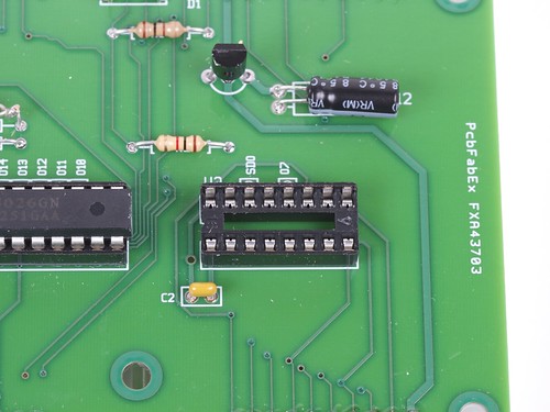
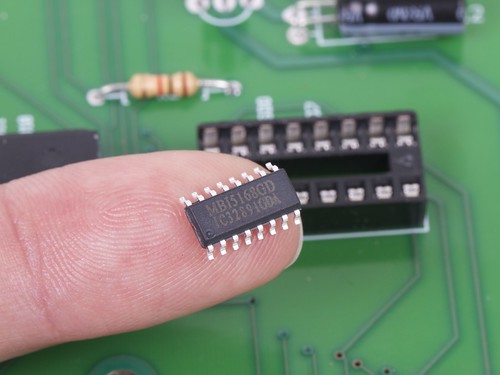 Doh! We’ve got the right chip handy, but only in the wrong package!
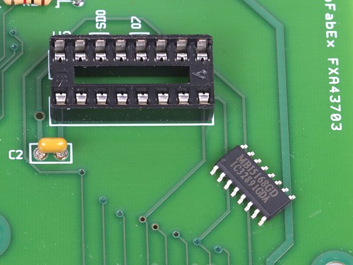 No siree, that chip will not fit in our socket. :(
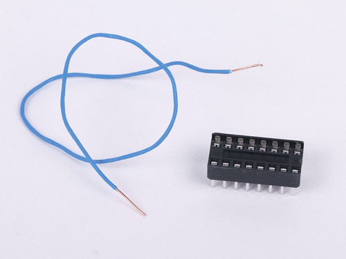 Fortunately, we’ve got tools: some thin copper wire, a spare DIP socket, and a few minutes of time. So, even without a readymade SOIC-to-DIP adapter, we’re still good to go.
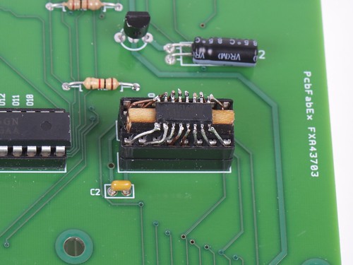
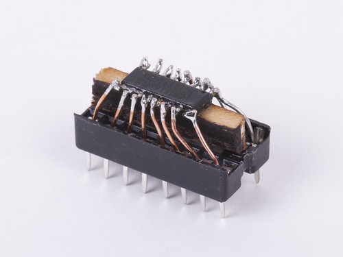 It’s helpful to raise the little chip up a bit with a wood or plastic shim, and then to fix it in place with hot or super glue. Strip the insulation off of the wire, and cut into small sections. Starting at the center of the chip, insert one end of each little wire into the socket and solder the other end to the matching pin of the IC. Trim the leads just above the chip.
And (poof!) it fits in the circuit board after all.
Beautiful? Heck no. (More like slimy but satisfying.) But finding a way to get your circuit board to light up without a few more days for the “right” chip to show up can be a wonderful thing indeed.
ComBots Cup VI

This weekend is ComBots Cup VI at the San Mateo Expo center. This event is eloquently described over at Suicide Bots: “Dozens of robots makers from all over the globe have cast common sense to the wind and scattered the contents of their bank accounts in sacrifice to The Robot Gods in order to bring you one amazing weekend of total mechanical ridiculousness in the form of ear-searing, heart-stopping, insurance-adjuster-apoplexy-causing Robot Combat!”
The event runs Saturday and Sunday from 2 pm to 7 pm and advance tickets are available here.

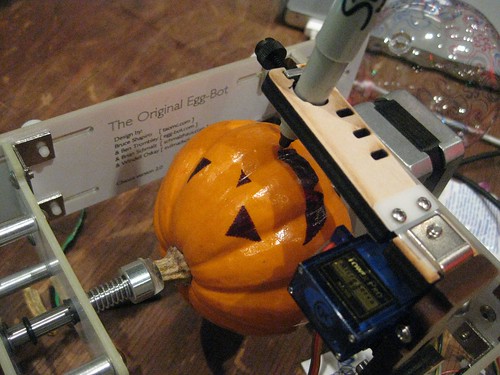
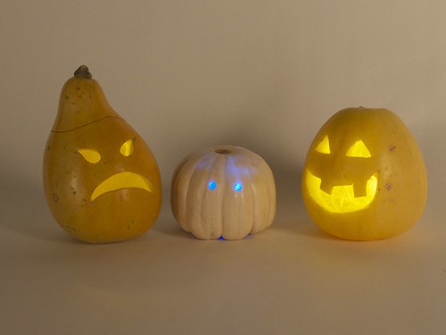
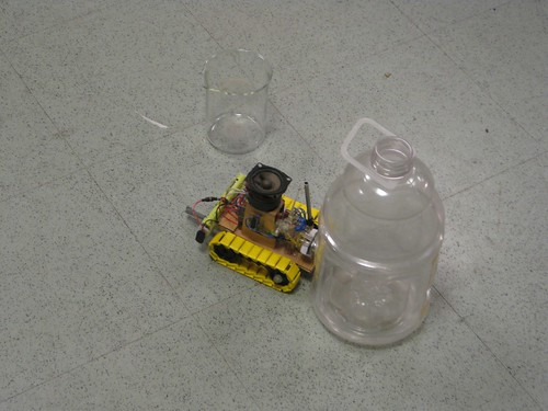
We’ll be running a few robots of our own (vs. eggs and pumpkins–not an entirely fair fight) and will be bringing robots and robot accessories for your last minute Halloween decorating needs. Hope to see you there!
Halloween Projects from Evil Mad Scientist Laboratories
The Great Evil Mad Scientist Laboratories Halloween Project Archive!
Halloween is one of our favorite holidays, and our collection of Halloween projects continues to grow. Every fall we update it to include our latest projects for the season. In the list that follows, we’ve organized dozens of our Halloween projects into categories: costumes, pumpkins, decor and food.
Last updated: 10/2019.
Continue reading Halloween Projects from Evil Mad Scientist Laboratories
Eggbotting for Halloween
In preparation for Halloween, we’ve gathered our tips and tricks for plotting on pumpkins with an Eggbot.
We first demonstrated printing on pumpkins with an Eggbot last year at Maker Faire New York.
Continue reading Eggbotting for Halloween
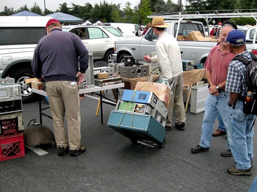
Last Electronics Flea Market of 2011, Saturday
Basics: Simple LED Pumpkins
Awesome little LED Jack-o’-lanterns are quick and easy to build yourself, in the tradition of LED throwies.
Special bonuses: (1) Now with candle-flame flickering LEDs and (2) way brighter than those little LED tea lights!
Continue reading Basics: Simple LED Pumpkins
Improving open source hardware: Visual diffs
As the open source hardware movement matures, it’s worth taking a moment to consider the issue of version control.
Collaborative software projects make heavy use of version control– tools like Subversion and Git, and project hosting sites like SourceForge, GitHub, and Google Code –to organize and manage the contributions of many developers to a project. But as we begin to consider open source hardware, can we use these same tools and sites for effective collaboration on hardware projects?
The short answer is, “yes”– after all, people are already doing it. But the reality is that we could do much, much better. Some people think that we do need a separate “SourceForge for hardware.” That’s hard to say. But it is the case– perhaps against conventional wisdom –that existing tools can be used, today, for meaningful hardware version control.
It’s certainly possible to take any old binary file (say from a CAD program), and store it in a version control system. This is, in fact, how many of today’s open source hardware projects are managed. However, a “diff” (direct file comparison) to see what’s changed between two versions of a given file is all but meaningless.
For design files in plain-text (“ascii”) file formats, such as Inkscape‘s SVG or KiCad‘s .brd, a diff is possible and is in principle meaningful, but it is usually all but useless in practice, because CAD is a graphical sport, and we need to treat it like graphics.
An example: Suppose that you found the following snippet in the difference between two SVG files:
 <path
       sodipodi:type="arc"
       style="fill:#ff00ff;fill-opacity:1;stroke:#ffa6a6;stroke-width:0.18000001;stroke-linecap:round;stroke-linejoin:round;stroke-miterlimit:4;stroke-opacity:1;stroke-dasharray:none;stroke-dashoffset:0"
       id="path2816"
       sodipodi:cx="237.14285"
       sodipodi:cy="328.07648"
       sodipodi:rx="160"
       sodipodi:ry="84.285713"
       d="m 397.14285,328.07648 a 160,84.285713 0 1 1 -319.999997,0 160,84.285713 0 1 1 319.999997,0 z" />
You probably wouldn’t recognize that (at least not quickly) as a big magenta ellipse. While it’s perfectly legible as source code, a diff result like this would be all but useless in practice.
The obvious solution, is to add in some visual diffs in order to make sense of changes between design files. On the bright side, making these is remarkably straightforward, and– with a little bit of effort –practically supported by existing version control systems.
In what follows, we’ll walk through some examples of visual diffs– with bitmaps and PDF files –and discuss what you can do to help make version control work better for CAD files, and to make CAD files better for version control.
Continue reading Improving open source hardware: Visual diffs
In pictures: Maker Faire NY 2011
A new Kraftwerk-inspired LED tie kit?
Well, almost— With a breath of new firmware, our Larson Scanner kit takes us on a trip to the late 1970’s.
In the old videos of electronic music pioneers Kraftwerk performing their classic The Robots, a prominent prop is the animated LED necktie worn by each member of the band. If you haven’t seen this, or it’s been a while, you can see it right here at YouTube. (Additional viewing, if you’re so inclined: Die Roboter, the German version.)
The Kraftwerk tie has nine red LEDs in a vertical row, and one lights up after the one above it in a simple descending pattern. And what does it say to the world? One thing only, loud and clear: “We are the robots.” Now, if you’re anything like us, the most important question going through your head at this point is something along the lines of “why am I not wearing a tie like that right now?”
The good news is that it’s actually easy to make one. And the starting point? A circuit with nine red LEDs and just the right spacing: our open-source Larson Scanner kit. With minor modifications– a software change and dumping the heavy 2xAA battery pack–it makes a pretty awesome tie. In what follows, we’ll show you how to build your own, complete with video.


