Forum Replies Created
-
AuthorPosts
-
ragstianParticipant
Hi Brian.
Thanks for the feedback, I will try the different suggestions to your ‘microstep’ fix – as a ‘hardware guy’ I just assumed the problem to be in the code!! – (As Jerry Pournelle (Byte Magazine – Chaos Manor – now Circuit Cellar) – once said “My favorite programming language is solder!” – ;-) ).
Will be able to have a closer look at the timing once I receive my Digilent Analog Discovery kit.An interesting observation when checking the different datasheets from Allegro is that in later versions of the motor driver chip there are a mode to avoid loosing steps in slow micro-stepping, see page 8 of this data-sheet; A4988 datsheet. I don’t know if this is applicable in this case.
I am aware of the limitations in the current settings – without the proper voltage or too high coil resistance you will never achieve the set current.
For other use of the EBB board an acceleration / deceleration feature would be nice. The motor is capable of high RPM but will have to be ‘ramped up’ and ‘down’ to avoid stalling or loosing steps.
Again; Thanks for the feedback, it’s really appreciated!
RGDS
RagnarragstianParticipantHi.
First “proof of concept” run of Eggbot Coilwinder complete.
I abandoned using the pen arm as a ‘wire guide’ as it was ‘fiddly’ and did not work very well due to the varying distance between the wire feed and the coil former. Made a ‘addon’ from Lego, the addon uses linear guides (Lego style ;-) ), the pen motor drives the ‘carriage’ by a string wound directly on the motor shaft. With enough turns around the motor shaft and a spring tensioner there are no ‘slippage’, the motor ‘stalls’ when preventing the carriage from moving without the string slipping on the shaft. The whole “contraption” is a ‘drop-in assembly’ and going from Egg-bot to coilwinder and vice versa takes less than two minutes. Next step is to make drawings and fabricate the parts from laser-cut plywood. Will have to decide what kind of rail system to use.
See images;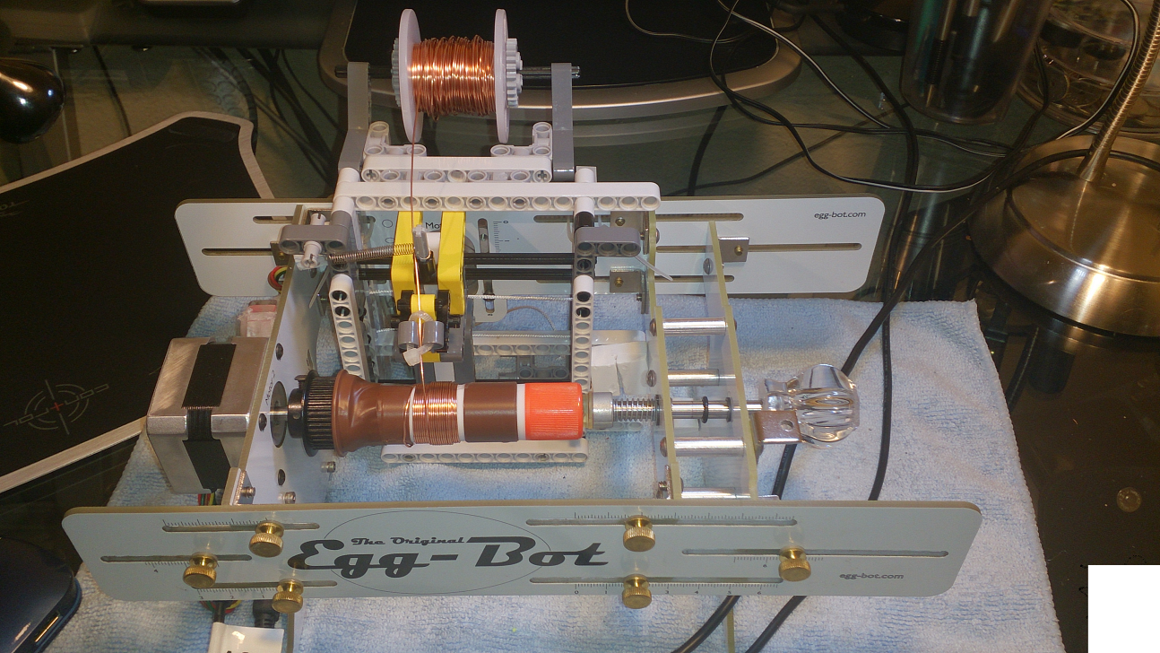
Pulley;
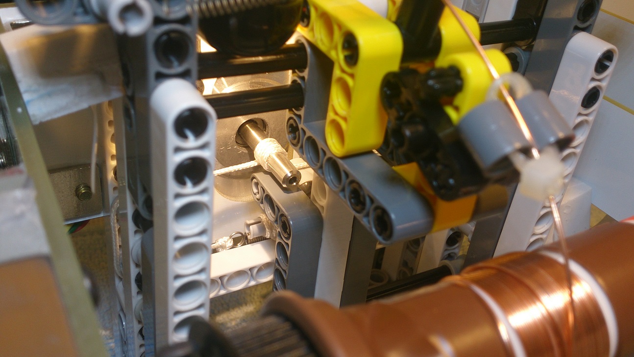
To get the coil-winder to wind in ‘wave’ pattern you just have to change the program for higher carriage speeds back and forth. I will have to study the topic further as there are a ‘lot’ of variables involved.
RGDS
Ragnar
ragstianParticipantHi.
As you see from the graph in the middle of the egg the “aspect ratio” is 1.5. The circles have to be ‘elongated’ 150% in order to plot as round circles on the egg. See this post as well.
Here are the text output of the plotted data;
Pen Radius; 31.50
Egg radius = 21.00
Egg length = 58.00At egg max diameter;
Step length pen = 0.99
Step length egg = 0.66
Aspect ratio = 1.50L= 0.01, Inkscape y value= 0.00, aspect ratio= 6.462
L= 3.75, Inkscape y value= 50.00, aspect ratio= 3.481
L= 7.50, Inkscape y value= 100.00, aspect ratio= 2.445
L= 11.25, Inkscape y value= 150.00, aspect ratio= 2.036
L= 15.00, Inkscape y value= 200.00, aspect ratio= 1.807
L= 18.75, Inkscape y value= 250.00, aspect ratio= 1.655
L= 22.50, Inkscape y value= 300.00, aspect ratio= 1.566
L= 26.25, Inkscape y value= 350.00, aspect ratio= 1.523
L= 30.00, Inkscape y value= 400.00, aspect ratio= 1.507
L= 33.75, Inkscape y value= 450.00, aspect ratio= 1.508
L= 37.50, Inkscape y value= 500.00, aspect ratio= 1.538
L= 41.25, Inkscape y value= 550.00, aspect ratio= 1.615
L= 45.00, Inkscape y value= 600.00, aspect ratio= 1.751
L= 48.75, Inkscape y value= 650.00, aspect ratio= 1.974
L= 52.50, Inkscape y value= 700.00, aspect ratio= 2.458
L= 56.25, Inkscape y value= 750.00, aspect ratio= 3.843RGDS
RagnarragstianParticipantHi.
Please be advised that the “aspect ratio” of 150% is valid only for the max diameter of the egg.
( Windell, you are absolutely right, 150% is spot on for a chicken egg with 42mm diameter and 58mm length. My previous value of 148% is only valid for a certain combination of egg diameter and egg length. Sorry – my bad! ;-) )
As the pen moves towards the ends the diameter of the egg gets smaller and the aspect ratio increases.
See my plot of the aspect ratio vs position. The software for plotting this graph is “still under construction” ;-)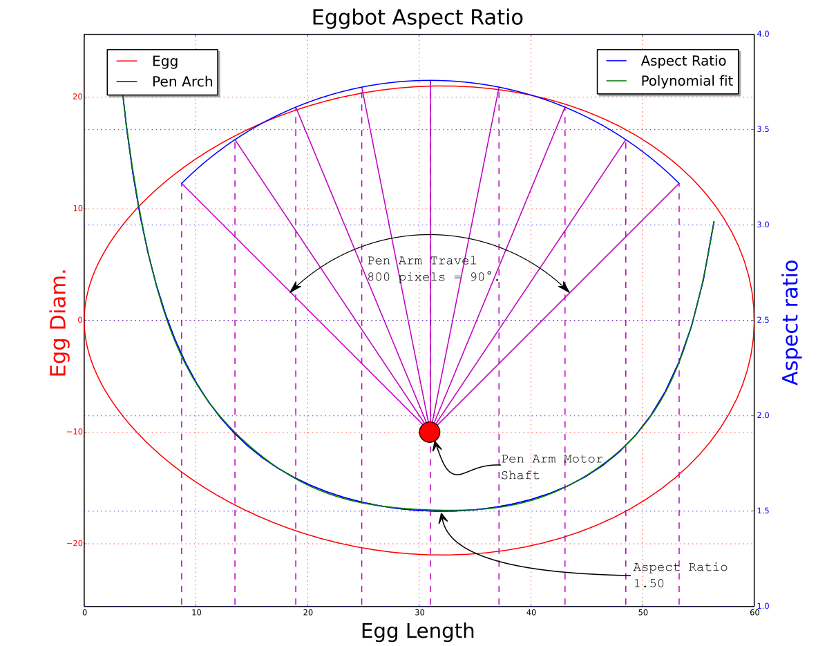
Using the values from this plot I created a file in Inkscape where the circles to be plotted looks like the image on the left, the result on the egg: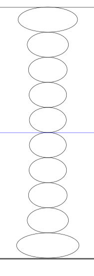
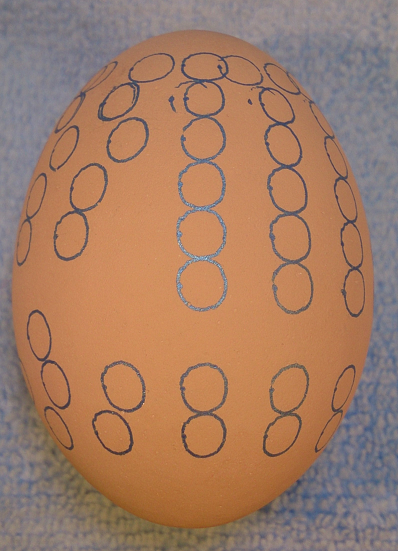
Never mind the bad plot quality!
Still experimenting with the plot and the values. (The larger circles at the top is the result of plotting the aspect ratio curve “backwards” – The highest AR values are in the ‘pointed’ end of the egg, opposite of what was plotted. The version above is updated but can still contain some “Id Ten T” errors (Replace the Ten wit numbers).
RGDS
RagnarragstianParticipantHi
Great idéa. Not much of an adaptor is needed really.
If the pen arm horizontal part had a “V” shaped “hole” (to take different wire diameters) to guide the wire you would only need a ‘device’ to keep tension on the wire.
As the pen arm is moving along an arch rather than in a linear fashion the program driving the ‘egg-winder’ would have to take that into account to position the arm correctly.
To get the coil former to stay between the egg couplers just two cones could be used, by having different diameter cones you would be able to use a wide range of coil formers.
Stay tuned for an Inkscape “winder” extension.RGDS
Ragnar
ragstianParticipantHi.
When examining your “Calibration Plot” and really trying to understand how the diameter of the egg affects the shape of plotted objects I made a small program in python to plot the values.
I have used a term I called ‘Aspect Ratio” which is the length of a line segment made with 1° of travel along the pen axis divided by the length of a line segment made with 1° of egg rotation. The aspect ratio is plotted as a function of position on the egg.
To have a circle appear to be round in the middle of the egg it has to be drawn as an ellipsis which is 1.48 times as wide as it is tall. At the end of the eggs the value changes to around 2.4
See illustration.

The plot is based on a chicken egg with 42mm diameter and 58mm length.
(To read the diameter from the plot you have to go from negative value to positive along the y-axis.) I have the pen motor shaft set 10mm lower than the egg-motor shaft and about 2mm from the middle of the egg along the length of the egg for minimum “tracking error” with this egg size.
(Red line represent the egg shape – ☺)
XKCD Style PlotWill make a ‘Calibration plot” based on the values from this plot for verification, stay tuned.
RGDS
RagnarragstianParticipantHi
You are doing it right setting the arm to 90° when the pen is down. I use the “paper under the pen” trick as well.
Make sure your pen tip is in the center of the egg along the ‘long’ axis (from tip to tip).The pen arm motor height is also ‘critical’ as the pen will move ‘across’ the egg when moving the pen arm from one end to the other. I use a pencil to check this as the line can be erased. Set the pencil tip on the egg with motors off and move the pen arm manually from end to end. If the line drawn on the egg has a ‘S’ shape the motor height is incorrect. (You can also observe the pen arm moving up/down). It takes a few tries to get a fairly straight line.
Good Luck
RGDS
RagnarragstianParticipantHi.
From looking at your egg I would suggest you check two items.
First the servo pen up and pen down positions has to be set fairly correctly.
I set the up position to lift the pen just a few millimeters off the egg surface and the down position so the servo arm clears the pen arm (horizontal part) by a few millimeters.
Next you have to make sure the delays is set correctly, for a felt tip pen the delay after pen down is “critical”. If the delay is set too long the ink will spread from the pen tip before the pen starts moving making a visible “blob” at the start of the line. If set too short or low the pen will start moving before the pen touches the egg making a ‘tapered’ line start.
Same goes for the delay after pen up, I suspect your setting is too low causing the pen/egg to move before the pen is lifted completely off the egg surface.Here is what I use at the moment;
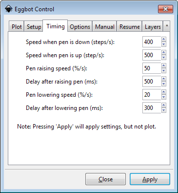
For your pens the delays and speeds might need some ‘tweaking’.
Good Luck.
RGDS
RagnarragstianParticipantHi.
“404
YOU HAVE REACHED THE END OF THE THINGIVERSE.
THERE IS NOTHING AWESOME HERE…
YET.”The correct link.
Nice work!
RGDS
RagnarragstianParticipantHi.
Yes, we are interested. Please upload.
RGDS
RagnarragstianParticipantHi.
Thanks Windell, I’ll take that as a compliment!
I rather trade “wearing out” a servo every four years for high quality plots.
The servo is a “low cost” item anyway, some of the pens I have experimented with costs more.
Having a servo and a few other “bits & bobs” in spare comes in handy.RGDS
RagnarragstianParticipantHi.
Getting a reply from “daxbot” is higly unlikely – the stats from the forum states that daxbot’s last visit to this forum was in October 2012.
quote from earlier post in this thread;
We can certainly create new fonts and characters, and there have been
other requests to do so. Probably the first step should be to build a
modern Hershey font editor– perhaps based in Processing –so that we
can begin to add these and other requested font characters.The best bet to get accented characters in the hershey extension would be to have WIndell generate it.
He is the original author of the extensions and have the knowledge and possibly code to “translate” a regular font into the hersheydata.py file needed by the extensions.
Windell – what if we say “Please”? (We can even send you some “Hershey” bars!)
I know that this will be “a project for a rainy day” and as such has got low priority.RGDS
RagnarragstianParticipantHi.
Just tested my eggbot with a 9V supply, no problems plotting.
RGDS
RagnarragstianParticipantHi
Your supply is probably OK for driving the eggbot. The problem seems to be your current potmeter setting.
With the pot at maximum the current to the motor is too high – the driver chip protection circuitry kicks in – causing the jittering. Try setting the pot to 11 o’clock position (full travel from approximately 8 to 4). On my ver13 boards this results in a current around 570mA which works nice.
(Please be aware that the silkscreen print on the board with indicates counterclockwise rotation for increase in current is incorrect.)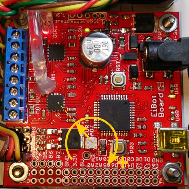
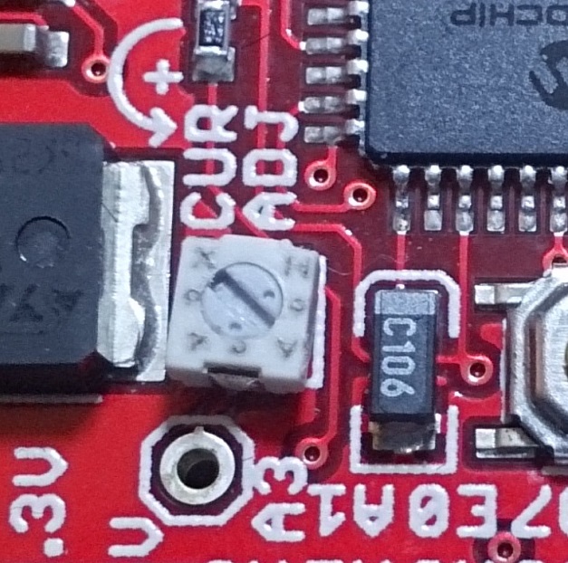
Good luck. Please feedback on results.
RGDS
RagnarragstianParticipantHi
Thanks, just an 18 hour drive!
I’am on my way!RGDS
Ragnar -
AuthorPosts


