Forum Replies Created
-
AuthorPosts
-
ragstianParticipant
Hi.
Ingenuity unlimited!!
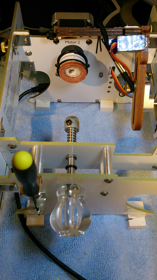
(This reminds me of my wood routers, the cost of the router itself is “nothing” compared to the cost of all the accessories – like bits, jigs, tables, fences etc!)From your picture I see one thing that caused me (your mileage might vary) problems in the beginning – the “egg-coupler” – whigh was always slipping. As a remedy I bought the “precision coupler” which at the time consisted of a 1″ toothed belt drive wheel. (See image further up in this thread) I removed the abrasive paper which got “slippery” as the abrasive wore off/filled with eggshell dust. In place of the abrasive pad I glued a rubber garden hose gasket (US) – after this mod the eggs are “self-aligning” and needs very little “tweaking” to get them centered. The new “precision-coupler” made of alu is very nice but the diameter is to small to give me the “precision” I want! I mount the eggs with the “butt-end’ towards the motor to increase the area in contact with the egg. To avoid using the “reverse motor direction” in the eggbot extension I have reversed the leads to one of the motor coils.
Two more changes I have made “pimping my bot”;
Added a drawer-pull knob to the spring loaded shaft, makes it a ‘breeze’ to “install” the eggs – with the motors disengaged the knob can be turned to check egg alignment as well. The knob is hot-glued to the shaft. Home-Depot sells the knob I used (US).
Next “upgrade” consists of feet made of erasers – this cuts the noise from the motors considerably. (try lifting the bot off the desk while it’s running to hear the difference). I have ‘mounted” the feet by hot glue as well, not a very good method as the hot-glue does not stick to the erasers.See picture;

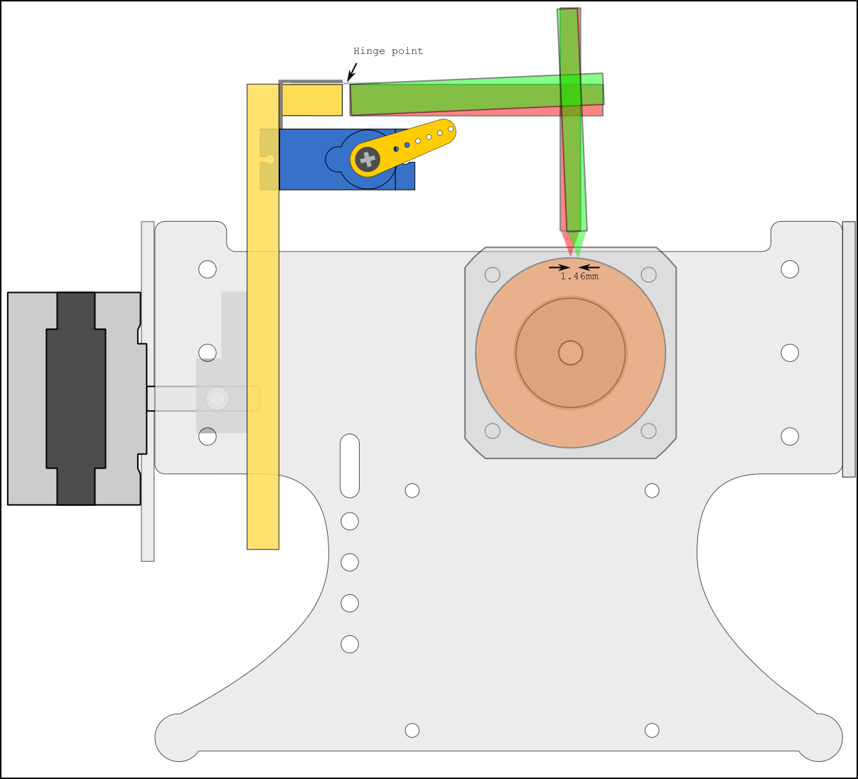
Made a quick Inkscape drawing of the eggbot with a 42mm diameter egg and a pen height error of 2mm.
To compensate for the difference in pen height the pen arm has to swing 2.5° which in turn causes a pen alignment error of 1.46mm.
Picture;
To me “bumping” the laser seems more likely than “bumping” the paperclip but the “imponator effect” of the laser are a couple of magnitudes higher!
RGDS
RagnarragstianParticipantHi RayT
quote;
“The question came up yesterday when I was asked to bring the bot to a
preschool shindig and do something for each of some 30 kids, only having
an hour and a half to complete.”Where are you? I’ll bring my bot and join you!
RGDS
RagnarragstianParticipantHi
That explains why setting some of the options in the code does not produce the expected result, for instance setting
bDryRun = True # write the commands to a text file instead of the serial port
does not redirect the output but causes the extension to fail.
Does the original code (from before it was stripped) still exist?
Would be nice to have the option to write to a file in order to make multiple identical plots later using the command line.RGDS
RagnarragstianParticipantHi dnewman
Clever indeed. Like your comments in the code about the software patent ‘troll”!
For the multi-bot setup to work on Mac / Linux this will have to be incorporated in the eggbot extension.
From other threads on this forum I see that the inkscape eggbot extensions are “stripped to the bone” to aid code reliability so this might/might not make it to the “official” code.RGDS
RagnarragstianParticipantHi.
Thanks, got it working – sort of – not getting the “The image has been resized to fit the image” yet.
Edit; got it! Thanks for the “pointers”! This is what I like about forums – learning something new every visit!
RGDS
RagnarragstianParticipantHi.
I have seen this ‘error’ on many of my plots as well.
The error is caused by different pen height when installing the second pen.
If the pen is just a tiny fraction off compared to the first one this will be the result.
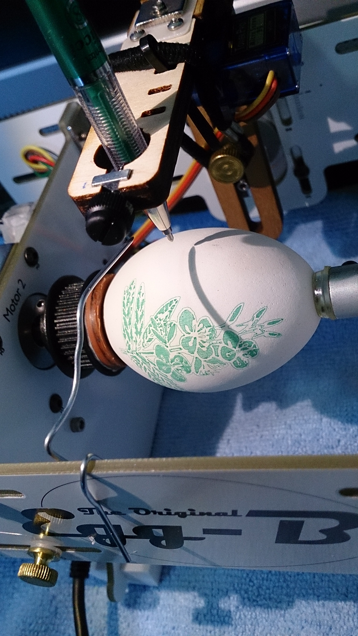
I use a bent paper clip and a point source light (LED lamp) to align the pen, see picture.
When the shadows meet I have the correct height. (I align the shadows by moving the lamp before starting the first plot – but after I “Enable Motors” in the “manual” tab of the eggbot dialogue.) For this procedure to work the pens have to be the same type as a difference in diameter will throw the “calibration” off. It’s also important not to move the light and/or eggbot during the plot. The egg have to be in the same position as well as most eggs are not perfectly round. (My eggs are ceramic eggs bought at Hobby Lobby. They have the same “perfect imperfections” as “real” eggs.)
By the way, how do you get your images to show in the posts?
RGDS
RagnarragstianParticipantHi.
Interesting question.
I have just tried this on a Windows7 system and it works like a charm!
The difficult part is to know which plot goes to which bot!
(If you plot the same design to the same media it would not matter.)Some methods to get the right plot to the right bot;
For the example let’s call the bots Bot_1 and Bot_2, the Inkscape “instances” will be called “Inkscape_1” and “Inkscape_2”. The intention is to have Inkscape_1 plot to Bot_1 and Inkscape_2 plot to Bot_2.By having only Bot_1 plugged in and starting the plot from Inkscape_1 starts the first plot to Bot_1.
Then plugg in the Bot_2 and start Inkscape_2 by clicking on the SVG file you want to plot. This starts another “instance” of Inkscape. By starting the plot from Inkscape_2 before Bot_1 finishes will get the correct plot to Bot_2.Another method is to have the first bot on the lowest number USB port as the eggbot extension polls from a list of available ports starting with the lowest number, once it finds an EBB board it starts sending commands. (Windows will then “lock” this port until it’s no longer used or “closed” in “geek” lingo).
Unfortunately there is no way in the eggbot extension to avoid closing the port when a plot is finished.
( By use of a small python program to open the ports and keep them open until ready to plot a more advanced system can be devised, however with my limited brain capacity and multitasking ability I reckon juggling two bots and two programs might be more than enough ;-) )This might work differently on Linux & Mac as the “locking of ports” might work differently.
When running a standalone program talking to the eggbots the output will look like this with two bots plugged in; (The USB ports will “look like” com ports when the EBB is plugged in.)
Com ports available on your system; (‘COM1’, ‘COM4’, ‘COM10’)
testing: COM1 for EBB Board
testing: COM4 for EBB Board
Found EBB on port: COM4
EBBv13_and_above EB Firmware Version 2.2.3
Current setting: 569.23mA. Motor supply voltage: 11.87V.Here the two bots are plugged in to COM4 and COM10. Com1 is a “regular” com port. while COM4 and COM10 “comes and goes” as the EBB boards are plugged in or out, one physical USB port will always be listed as COM4 and the other physical USB port always as COM10. By plugging in the bots to different ports other numbers will appear.
(Please note that it is NOT recommended by EMSL to flash the EBB board with higher versions than 2.0.1 until later versions are verified to be “bug free”)Good Luck plotting several eggs at once!
RGDS
RagnarragstianParticipantHi.
From the kit page;
The circuit runs on 2 AA cells, and has an external battery box with
integrated power switch. Under high-brightness mode: A new set of
alkaline AA cells would be expected to last about 60-80 hours
continuously, or 10-13 days if run 6 hours per day. Under low-power
mode– the default at turn on– a new set of alkaline AA cells would be
expected to last somewhere in the neighborhood of 400-700 hours, or
16-30 days if run continuously.10 to 13 days if run continuosly 6 hours per day or in other words 5 to 6.5 days at 12 hrs per day.
Bring one set of spare batteries anyway. (Better safe than sorry!)RGDS
RagnarragstianParticipantHi.
When having serial or usb problems on other platforms one trick is install a ‘monitor’ to see all ‘traffic’ on the port.
One such goodie for the Mac; Port_MonitorGood Luck
RGDS
RagnarragstianParticipantHi
As stated above;
Your “design” can be plotted on the eggbot with just a few changes to some of the parts.
The eggbot does not produce “filled in” parts. The fill-in has to be added manually.
To change your design I would set the fill to none and stroke to a high contrast color.
Then I would select the path and do a duplicate and then inset (by two pixels).
Add Path effect – Hatches (Rough)
Then do a Extension – eggbot – preset hatches for fills.A few manual edits has to be made to the design as the hatching function is not (yet)
“smart enough” to avoid hatching in the closed areas inside (like lakes on a map) the outline.The plot of your design (I did not ‘extract’ all the ‘lakes’ in the left part –
will leave that as an exercise for you!).
Same goes for the leaves in the plant – I filled in a few – you can do the rest ;-)As you see on the right part of the plant – the pen tip is too coarse to get all
the fine details, I have removed some on the left part for comparison.
More of the fine details has to be removed or the paths has to be moved further apart to get a decent plot.I have also stretched the designs along the x-axis to get the proportions more “correct”.
The file as plotted; SVG_File
To get a ‘better” plot you will have to edit the file some more. The red “Art” is still a disaster – needs more work.
Results; part1 part2 part3
As you see the eggbot extension is “unforgiving” – it plots even “invincible lines” that is lines with no stroke or fill, One of the squares around the “red” object had no stroke and was not selected when I moved the rest.RGDS
RagnarragstianParticipantHi Brian.
Thanks for the feedback, I know there are too much info to digest in one go!
No rush on the answers.
My code for the “automatic check of the motor voltage before plot” is almost finished, it now works with all the firmware versions I could find on the net. For the hardware I have “simulated” the earlier and later versions. Both my EBB board are ver 13.RGDS
RagnarApril 6, 2014 at 2:57 pm in reply to: 400 steps / revolution steppermotors higher speeds than 1000 steps per second #21787ragstianParticipantHi StefanL38.
Good catch on the coding.
Using “hard-coded” values in (any) code is a ‘pain in the neck”.
It’ is used “all over” in the inkscape extensions,
I have changed most of my extensions where I need higher default values – like in the
“Render – Parametric curves” the max value for the independent variable “t” is 1000,
if I use the “degrees” option this will plot less than three “revs:” I have set it
to 100000 in the “param_curves.inx” – I then store the extension files in my %appdata%
folder (“C:UsersRagnarAppDataRoaminginkscapeextensions”on my win7 system)
– the files here will not be deleted by uninstall / install of Inkscape.
You can do the same to increase the too low step/second value in the eggbot.inx file.
Having experimented with higher step values in my standalone driver program my motor fails to move fast as it is not accelerated or ramped up/down.
How do you overcome this?For the pen arm play you will have to ‘design out” the play.
I agree that the original design is “clever” and very simple doing a very good job.
Two changes to the original design would be beneficial.
In the original design the pen tip moves along an arc when the pen is lifted, when changing pens the getting the “new” pen height just a tiny fraction different from the previous pen height will introduce a “large” offset along the X-axis. I am working on a design where the pen moves straight up/down when lifted/lowered to remedy this. (there are already one in thingiverse).
Another “problem” in original design is that it’s possible to “twist” the pen along the x-axis as the hinge part is not stiff enough. (using the optional “stiff” hinge almost eliminates this problem though).
I use extra force (provided by a rubber-band) to keep the pen down as some of my pens require this “extra” force to work.
The RC-Servo does not “like” the constant force provided by the rubber band in the up position.I try to come up with something “simple” that can be mass-produced using the existing technology (laser cutter) of EMS.
Currently I have a design on my napkin using a wedge (moved by the servo) lifting the pen.
Another change I would like is to move the pen arm servo off the pen arm to reduce the “moment of inertia”.
By having the servo link operating in the center of the pen arm motor axis the servo can be attached to the eggbot frame.Good luck “pimping” your eggbot ;-)
Thanks to the EMS team for providing me hours and hours of fun!
RGDS
RagnarApril 5, 2014 at 10:22 pm in reply to: 400 steps / revolution steppermotors higher speeds than 1000 steps per second #21784ragstianParticipantHi
I plot designs 6400 wide on my 3200 pixel eggbot (1.8° motor) without problems
( with the “Wrap around” option enabled )The largest canvas size I have used was 32000 pixels (to get a 10 turn spiral of text on the egg – the text go between diagonal corners).
What happens if you plot a continuos line?
I might get a 0.9° motor for some experimentation, reckon the added resolution won’t be of much use since the arch length for a 48mm diameter egg will be 0.047mm/microstep for the eggmotor and 0.069mm/microstep for the pen (70mm dia circle). What’s your experience plotting with this motor (apart from the above problems).
RGDS
RagnarApril 5, 2014 at 4:53 pm in reply to: 400 steps / revolution steppermotors higher speeds than 1000 steps per second #21782ragstianParticipantHi.
Have you selected the “Egg (x) axis wraps around” in the options tab?
RGDS
RagnarragstianParticipantHi.
Experimenting with the EBB board and “extending” my test program I discovered that the pulse output from the EBB is acting a “little strange”. When pulsing at a low rate the pulses stop briefly every 16th pulse causing the motor to “stop” briefly every 1.8 degree of rotation. Driving a camera pan head the stops can be easily seen in the video recorded. I reckon the “jitter” or stops also happens at higher motor speed.
Without access to a oscilloscope or logic analyzer it’s difficult to estimate the duration of the stops. For smooth operation I am assuming the spacing between the end of a “major step” and the beginning of next “major stap” has to be the same as a between micro-steps, Is my assumption correct?When experimenting with different stepped drivers, motors and controllers it can often be difficult to figure out where the fault lies when the motor does not move as expected (sometimes it does not move at all!). Visiting different CNC forums over the years the need for a simple tester can be seen. Googling for a “stepper fault finding tool” came up with nothing so I set out with pencil and napkin and “designed” my own.
Result can be seen in this video snippet; Simple_Stepper_Driver_Tester.
The stepper tester is connected to the output of the stepper driver in parallel with the motor.
As can be seen in the video even the micro-stepping can be seen as varying intensity of the LED’s. (From approximately 0:30 when rotation changes to CCW) The micro-stepping can bee seen even better running the motor slower.
By removing power to the driver and rotating the motor (by hand) will cause the LED’s to light up if the motor is OK and wired correctly.
The (extremely complicated ;-) ) schematic for the tester will be uploaded as soon as I have translated “from napkin to PDF”.Have fun.
RGDS
Ragnar -
AuthorPosts


