Forum Replies Created
-
AuthorPosts
-
Windell OskayKeymaster
I’d suggest attaching the battery box via the USB 6-pin connector, using a 6-pin female header socket strip. Since you have the USB power jumper installed, you probably don’t need to run both power and USB at the same time.
June 12, 2012 at 1:40 pm in reply to: help needed to in getting Meggy RGB Jr. going (newbies) #20716Windell OskayKeymasterIf you managed to damage the first LED D1 when you soldered it in, you may want to be a little more gentle with your soldering– those don’t usually fail.
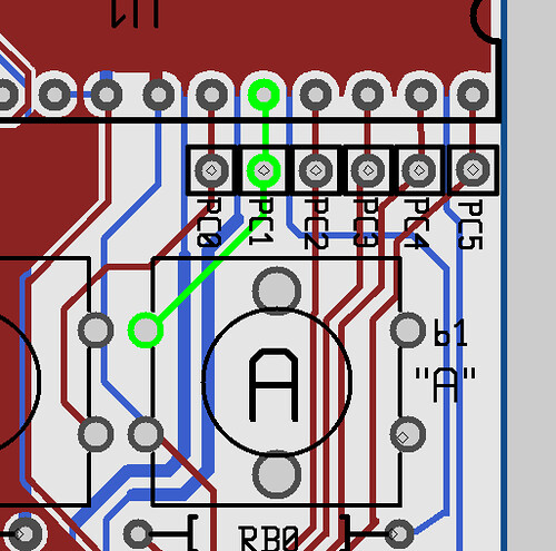
The connection of button b1 to pin PC1 is shown above. If you’re reading 0 V on that pin, then it is likely that there’s a bad connection between the two points. Check to see if there is actually a connection between these two points. (You can do that from the top or bottom of the board.)One pin of button b1 is connected to ground. Check to see if it is actually connected, say to the pin to the left of PC0.Then, check to see if this pin is electrically connected to the PC0 when the button is and is not pressed.Windell OskayKeymasterIt is likely that you have a short circuit somewhere in the control section that is holding the base of one of the transistors low– or just connecting it to a neighboring signal. This could be either at the transistor itself (which you have already checked) or at the pins of U2, the LED driver that controls the second row. If you have access to a multimeter, you might be able to use that to help locate the issue.
June 10, 2012 at 5:07 pm in reply to: help needed to in getting Meggy RGB Jr. going (newbies) #20714Windell OskayKeymasterThe correct behavior on startup is that D0, D1, D2, D3, and D4 should light up. So, it’s not that some of your LEDs are shifted, it’s just that one of them is not lighting up. Check the soldering at that LED location, and at the pins of the LED driver chips. Also make sure that that D1 is installed with the correct orientation.
Check the soldering at button “A” (aka location b1 on the circuit board) and the corresponding pin of the microcontroller, which is the pin located directly above the hole labeled PC1.You may also want to download the Meggy Jr RGB schematic, to help figure out where to put the multimeter, if you want to do this that way: http://wiki.evilmadscience.com/Meggy_Jr_RGBWindell OskayKeymasterVery nice!
-
AuthorPosts


