
The Evil Mad Scientist Thanksgiving Sale is running now through Monday. Coupon code TURKEY will get you 10% off sitewide, and we have a list of kits on additional discount on our specials page. Thanks for being our awesome readers and customers!


The Evil Mad Scientist Thanksgiving Sale is running now through Monday. Coupon code TURKEY will get you 10% off sitewide, and we have a list of kits on additional discount on our specials page. Thanks for being our awesome readers and customers!

Introducing the Boldport Buggy kit.
This simple and playful soldering kit is based on the on the beautiful Buggy circuit board designed by Saar Drimer of Boldport.


The first version of this circuit board was created as a badge for the hardwear.io hardware security conference in The Hague. This new version of the Buggy is a complete kit, featuring an updated circuit board, with a power switch and six candle-flicker LEDs.

A cool detail is that its six legs are actually the current-limiting resistors for those six LEDs. They are posable (giving it quite a bit of personality) and we have given it little red tubing socks to cover up the otherwise-conductive feet.


The Boldport Buggy kit is available now at our store, and you can read more about its design at Boldport.
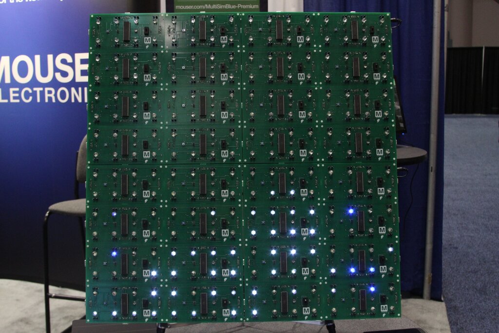
We dropped by ARMTechCon last week to check out a tip sent in by email (thanks, Barry!) that Mouser Electronics was displaying something that looked like our Octolively modules.
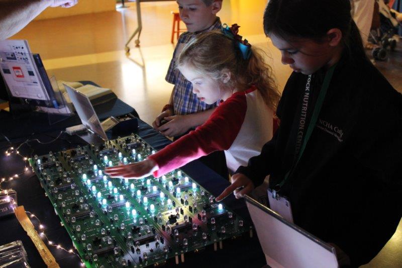
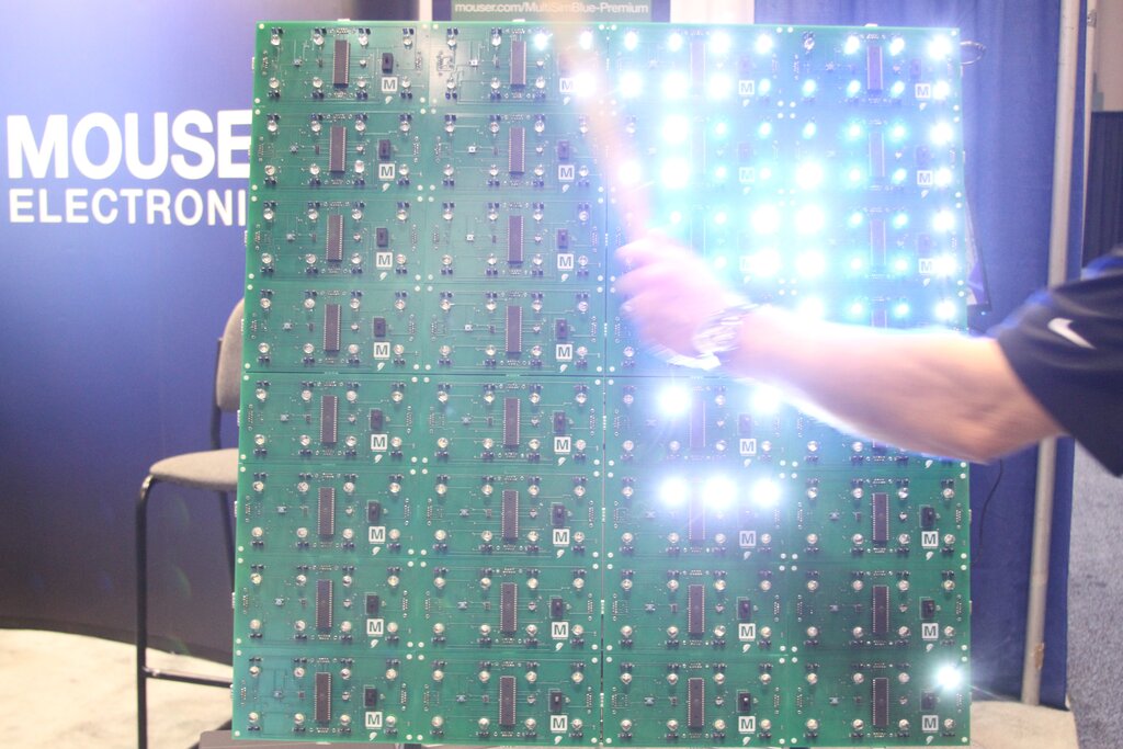
Mouser staff had been inspired by an installation of our Interactive LED Panels to create something interactive that they could show off at Engineers Week at the Fort Worth Museum of Science and History. They used the Octolively as the basis for their project, and the kids loved it of course.
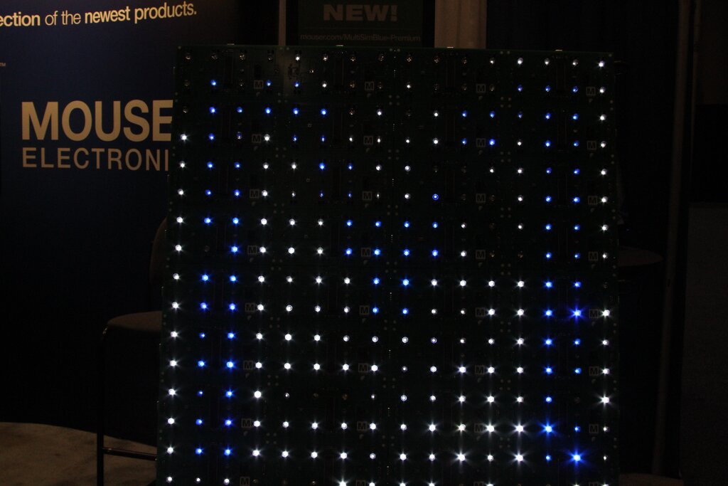
For trade shows, they built up a display with a mix of blue and white LEDs to show off the Mouser “M”. Based on the foot traffic it got while I was at the booth, it is quite popular.
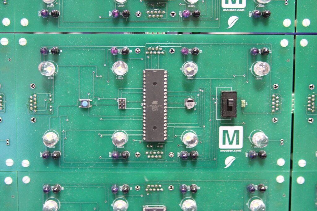
They made some minor changes from our original Octolively design and used different connector types to highlight Mouser’s product lines. The heart of the project is still the 40-pin DIP ATmega164P (perhaps anomalous at an ARM conference) running our Octolively code, which gave the Mouser folks a chance to play with some microcontroller programming.
It’s always exciting to see a derivative of one of our projects in the wild. Thanks to the Mouser folks for sharing their project story and sending the museum picture for us to share.
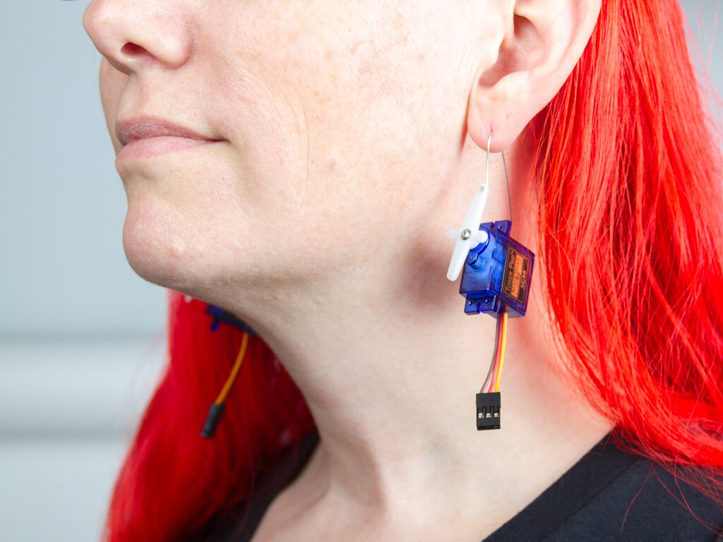
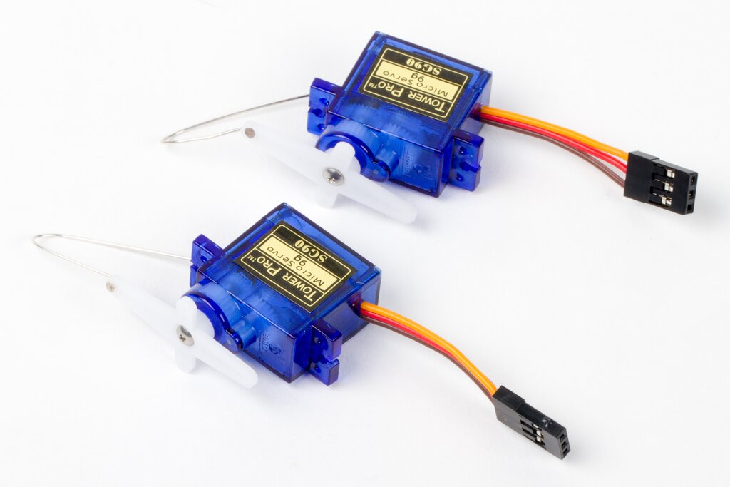
These earrings — Perfect for radio control and robotics enthusiasts — are made from little servo motors, partially hollowed out for lighter yet weight.
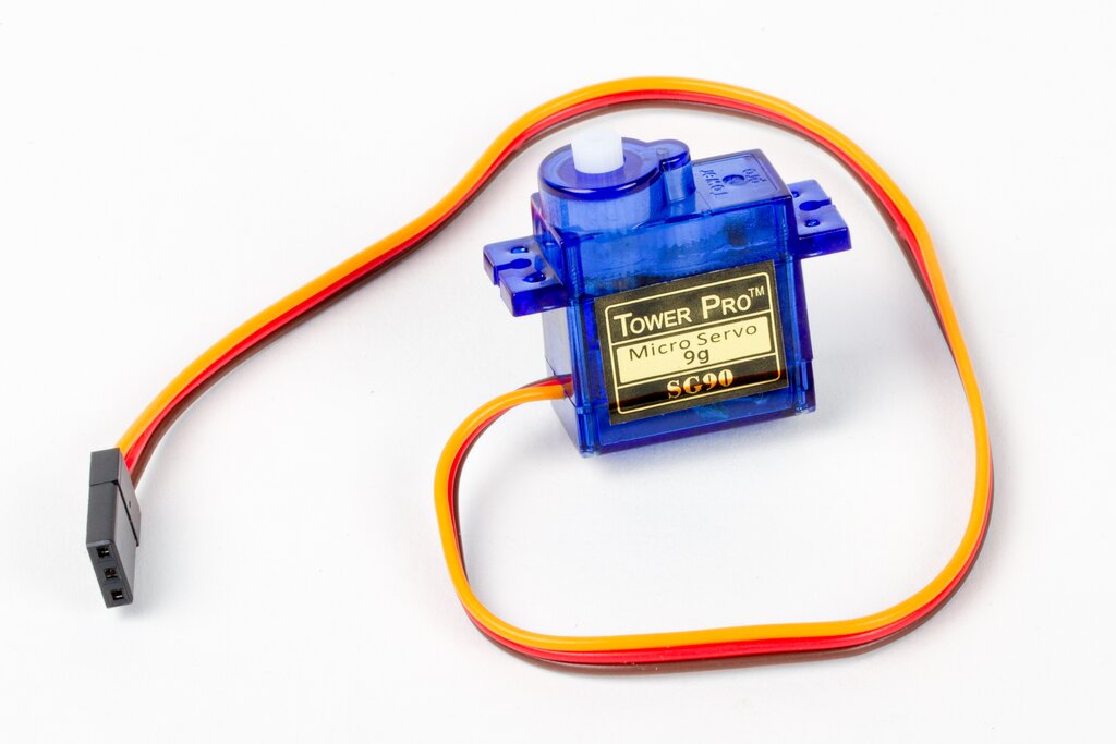
We begin with a “9 gram” class micro servo motors. This is a standard type of servo motor; the same kind that we use to lift the pen or brush on the EggBot and WaterColorBot.
Inside of one of these you’ll find the actual DC motor itself, a set of plastic gears, a potentiometer (pot) connected to the output shaft, and a little circuit board that controls it all. The gear train is used to convert the high-speed low-torque output of the motor into its high-torque low-speed output, and the pot reads the orientation of the output shaft so that it can be controlled (servoed) to the correct position. However for today, we’re primarily interested in the case, and most of what’s inside doesn’t really matter.
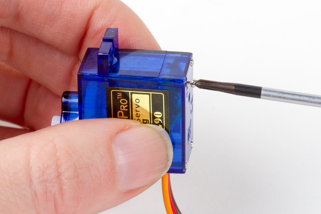

The lower part of the case comes off with four very skinny, very long screws.
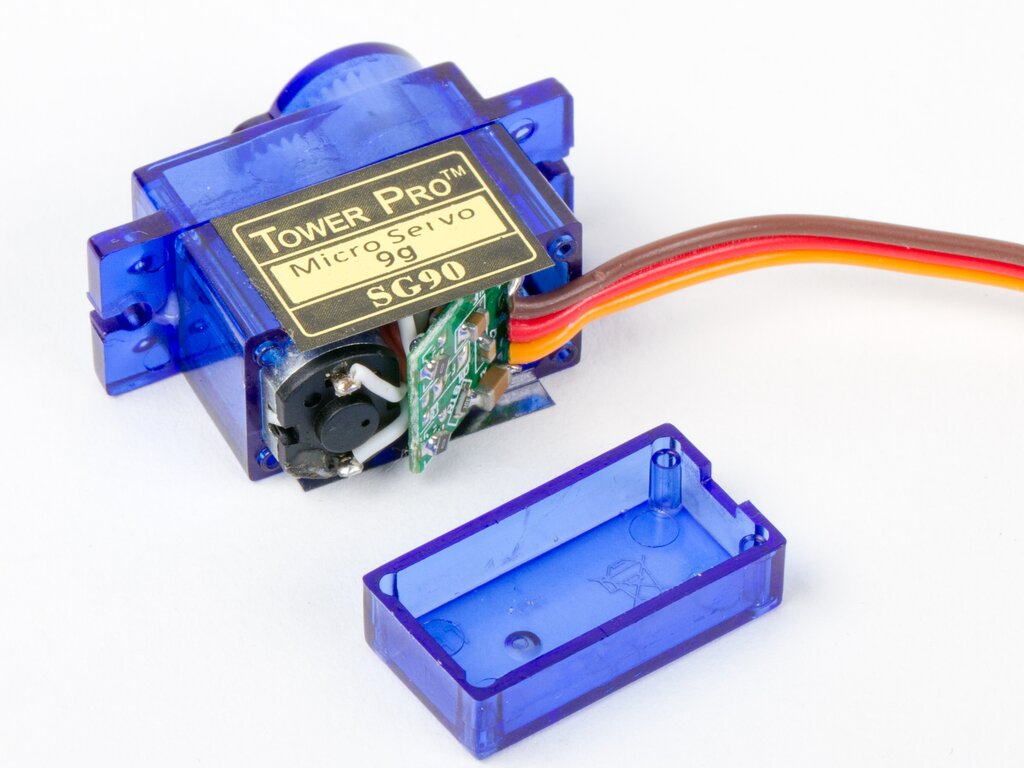
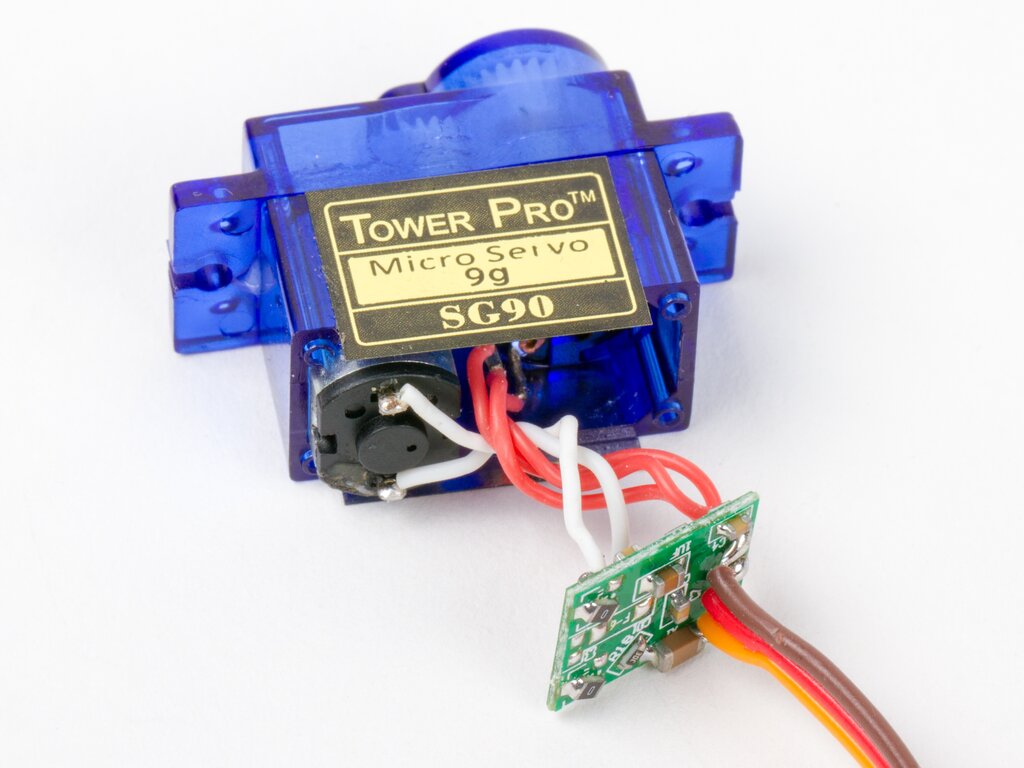
And then, you can pull out the tiny little circuit board.
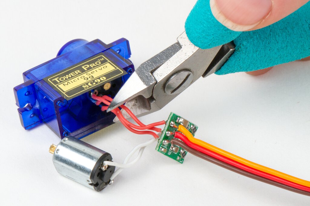
The DC motor slips out easily, but the three wires to the pot are soldered in, and need to be clipped.
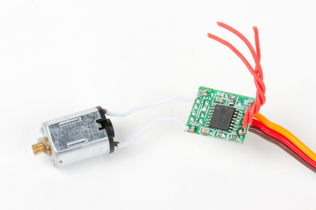
Incidentally, it’s straightforward to hack servo motors, repurposing the circuit board such that (1) the two outputs to the DC servo motor actually control something else and (2) that the input signal from the pot comes from something else. You can read our article about how to make a one-ton servo motor for a good example.
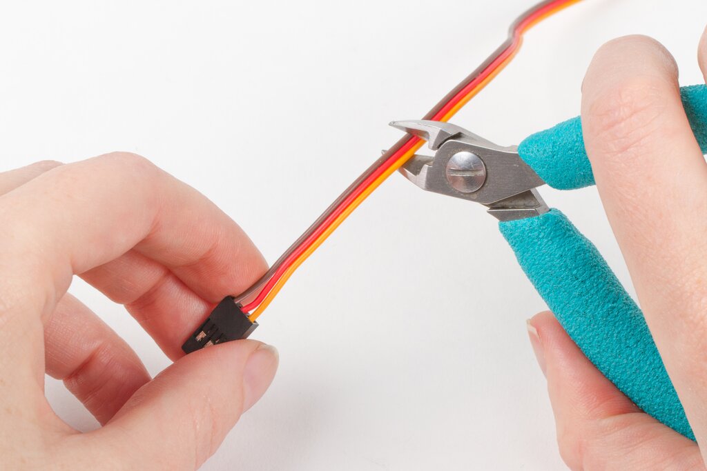
And then there is the matter of the cable. We don’t actually need that much cord hanging out the end — and it weighs something — so we can clip it shorter.
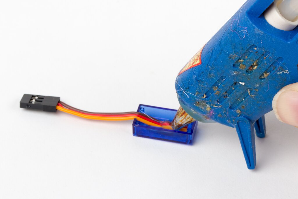
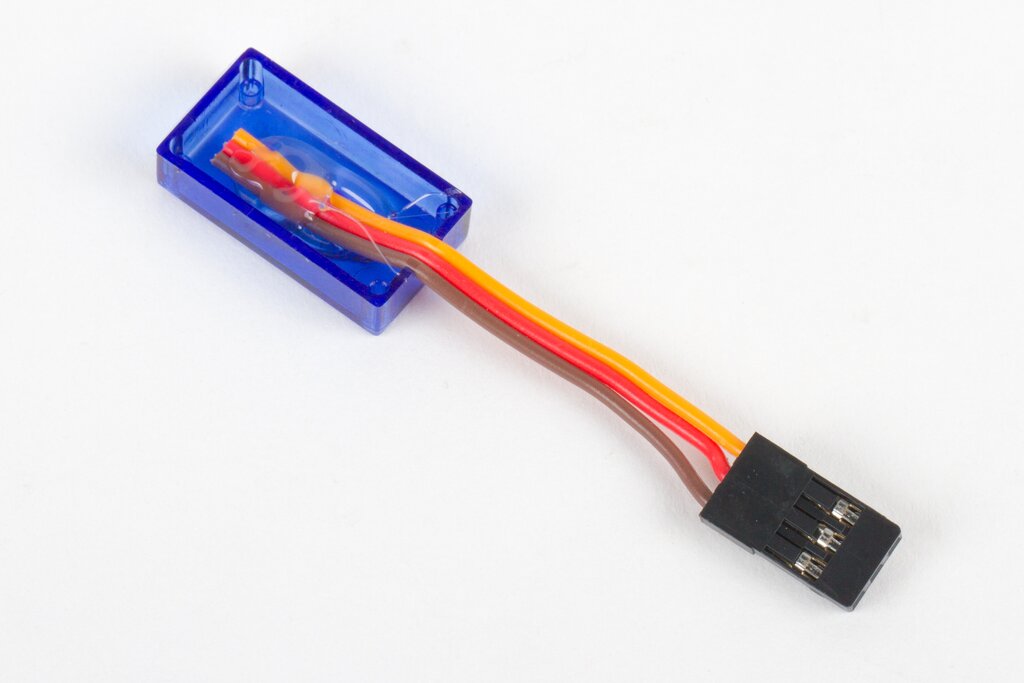
A dab of hot glue secures the cut-off end of the cable to the bottom of the case.
And the finishing touches: Reassemble the case, add the servo horns and finally the earwires. The final weight of each one is about 6.5 g, and the total weight of the components that we removed (motor, wires, circuit board, and cables) is about 5.6 g. As we have left it, the output shaft feels solidly held in place. Turning the output shaft still turns the gear train, and its motion is limited to the servo motor’s original range of travel; about 2/3 of a turn.
You can make it even lighter — all the way down to 5.4 g per piece — by opening it up further and removing the pot and all of the plastic gears except for the output shaft. It looks mostly the same from the outside (with the exception that the gears are no longer visible), but does not feel nearly as nice: The output shaft is only loosely held on its axis, and now able to turn freely through a full circle.
One might imagine taking it the opposite direction too: Building in a little battery and microcontroller, so that the servo motor would turn on its own while dangling from an ear. That version is left as an exercise for the reader, hopefully one with short hair that won’t get tangled.
If you liked this article, you might like some of our other related projects: Fimo fractal earrings, Chip earrings, Hard drive earrings, and Bobbin earrings.

The Annotated Build It Yourself Science Laboratory is included in the Humble Book Bundle DIY at the $15 or more level to support Maker Ed.
Lenore is interviewed in episode 42 of the Cool Tools podcast, talking with Kevin Kelly and Mark Frauenfelder about some of her favorite tools, forgetting what PID stands for, and gushing about coffee.

RJS sent in these pictures from Halloween this year after making our Larson Scanner kit in its Kraftwerk Tie incarnation.

Thanks for sharing the pictures, you both look awesome!
Windell is the guest on the most recent episode of Embedded.fm, titled Please Don’t Light Yourself on Fire. This episode’s contest prize is a signed copy of The Annotated Build It Yourself Science Laboratory.

Barnes & Noble is putting on a Mini Maker Faire next weekend at stores across the country. As part of the event, Windell will be at the San Jose store on Friday, Nov. 6 at 1 pm with The Annotated Build-It-Yourself Science Laboratory.

Ken Shirriff has written an excellent exploration of the 741 op-amp, including decapping a metal can package AD741. There’s a very cool interactive viewer so that you can click on the components in the schematic or on the picture of the die to see what each one is and does.
…The 25pF capacitor in the 741 has a very small value but takes up a large fraction of the chip’s area. You can see the capacitor in the middle of the die photo; it is the largest structure on the chip. …
Our very own XL741 is referenced in the footnotes, too.