
We are excited to join with the National Park Foundation to support the 2015 White House Easter Egg Roll! Read the press release for more information.


We are excited to join with the National Park Foundation to support the 2015 White House Easter Egg Roll! Read the press release for more information.
-500.jpg)
Vera wrote to us:
Having loads of fun with the wonderful EggBot! Some photos for you to enjoy.
-500.jpg)
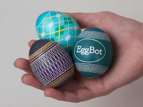
She’s posted some beautiful eggs, drawn on with a variety of pens.

There’s a fun series of ping pong ball gifs.

She also has used clear glass ornaments with an almost stained-glass effect. There are many more photos on her site, so check them out!

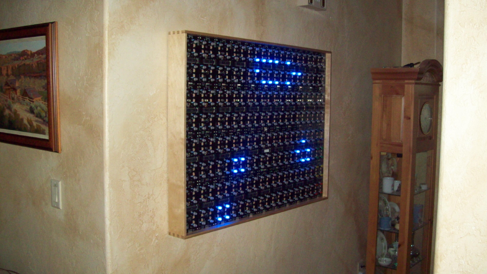
Forrest shared these pictures of his Interactive Game of Life build.
I bought the project to help expose my two grandsons to electronics and learn how to build circuit boards. Dan my 10 year old did one board all by himself just using your instructions. Josh my 14 year old did more than half of the boards and I finished them up because I only have the kids for limited time periods. I am so proud of them. Josh complete understands how the Game Of Life works…I don’t HA! We are planning on adding a instruction board to the bottom of the display so other kids can have fun.

I have a CNC router and built the frame. The boards are screwed onto a piece of 1/4″ plywood which floats in the frame. Not glue in. I machined a loose slot around the inside frame pieces. That way I can take the frame apart and easily change out of a board if necessary. It has been so much fun to build and you have SUPER service.
We thank you so much and would like to build more projects that you may come up with. As soon as I get more time with Dan we are going to build the clock.
He also shared his case design (105 kb dxf). Thank you for sharing your time and skills with your grandkids, and for sharing your pictures and design with the rest of us!
Kellbot posted this video of the EggBot drawing the lovely Paisley Flower Egg design she has up on Thingiverse.

It turned out great!

Our friend Schuyler hooked up our Meggy Jr RGB hand-held video game platform up to control the WaterColorBot. He wrote on twitter:
I got the @EMSL Meggy Jr RGB working with the @MakerSylvia WaterColorBot. My code is here. https://github.com/docprofsky/meggyjr-cncserver.

The output looks great, too. Thanks for sharing your code, Schuyler!


Happy St. Patrick’s Day! Thanks to A.Z. for sharing these photos of ornaments decorated with shamrocks using the EggBot.

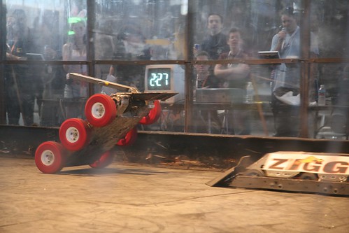
We’re excited to be attending and helping to judge robots at RoboGames this year. This epic competition includes not just combat, but also sumo, soccer, firefighting, and so many more. The event is April 3-5 and tickets are on sale now. Evil Mad Scientist readers can get $5 off with coupon code EMSL.
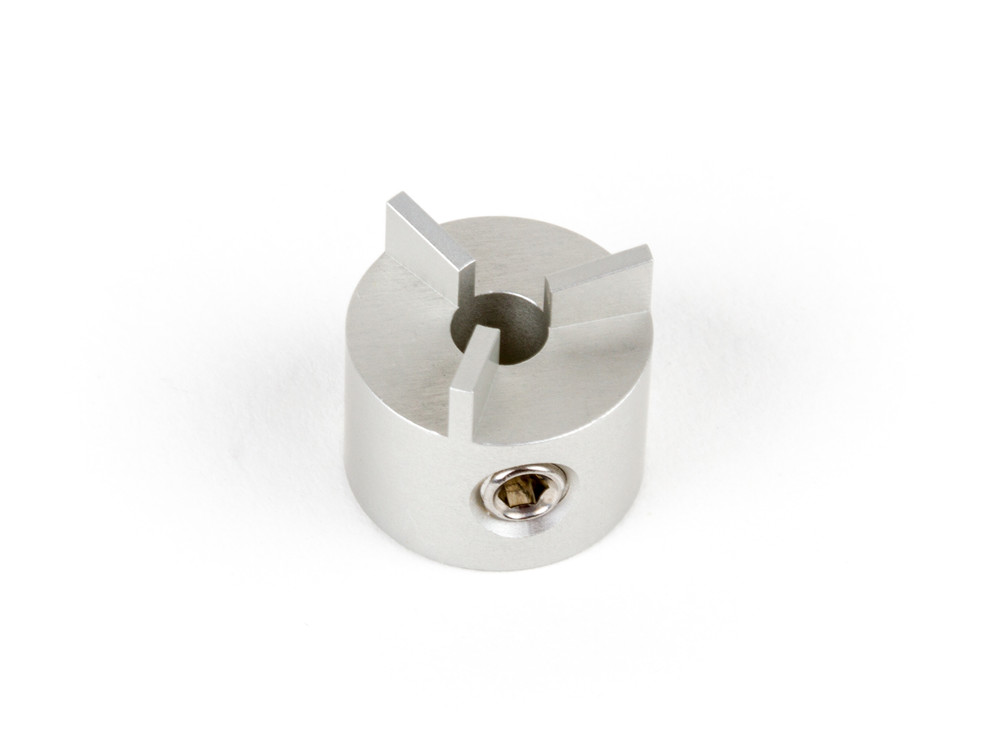
This tiny little thing is a new EggBot accessory that we call the Wax Coupler. Not because it’s made of wax (it’s CNC machined aluminum) but because you can use it to attach an egg to the motor that turns it, using wax, like so:


Aside: why is the base of the egg black? We’ll get to that below.
Once the egg is attached to the Wax Coupler, it provides a rigid attachment point that provides secure coupling between the egg and the motor. More importantly, the coupler+egg assembly can be removed from the motor and put back in place, without losing registration. In machine tool terms, you might describe this as the process of attaching an egg to a rigid mandrel.
Wait– why would you want to do that?
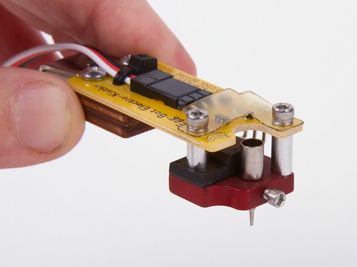
Let’s go back a few steps. Last spring we introduced our Electro-Kistka for EggBot. A kistka is a hot-wax pen used in the traditional wax-resist and dye (batik) method to produce colorful eggs in the fashion of Ukranian pysanky, and this one is designed to work with a computer-controlled EggBot.
At the time, we noted that this process introduces a new problem, that of re-indexing the egg within the EggBot, after taking it out for dyeing:
It is harder than it looks. While two-tone eggs are straightforward, we have found it to be challenging to precisely reposition an egg after removing it for dyeing. Thus, it takes considerable patience and experience to produce multicolor eggs with good registration between subsequent color layers. We’d be interested in exploring better ways to do this.
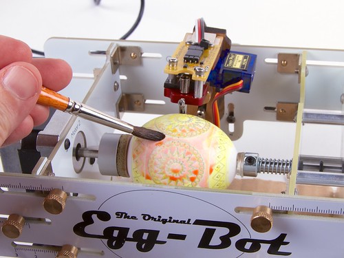
One method that we tried (shown above) was to dye the egg in place, by brushing it without removing it. The results were mediocre: it worked, but the dye layers were subdued and blotchy. We also looked into a somewhat wackier method of dying the egg in place, by standing the EggBot on end, and using a collapsable bag of dye.
Which brings us to the proper solution: To attach the egg rigidly to a repositionable coupler with beeswax. Doing so allows us to take out the egg and dye it (coupler and all) and then easily index it back into the EggBot.

We are very pleased to be amongst the judges for this year’s Hackaday Prize, which was announced today:
Last year we challenged you to build the next generation of connected devices. Six months later, the best teams and projects from around the world battled for the greatest prize of all: the respect of their peers and a trip to space. This year, we’re issuing a call to hackers, engineers, makers and startups from all over the world, to focus their creative efforts on nothing less than solving serious issues facing humanity.
Prizes this year include a trip to space on a carrier of your choice, a laser cutter, a builder kit (pcb mill, 3d printer, cnc router, bench lathe), and tours of CERN in Geneva or Shenzhen in China. New this year is a “Best Product” award. Show a production-ready (and ideally, open-source) device and you can win $100,000 in addition to being eligible for the other prizes.
You can read more about the contest and sign up at http://hackaday.io/prize
