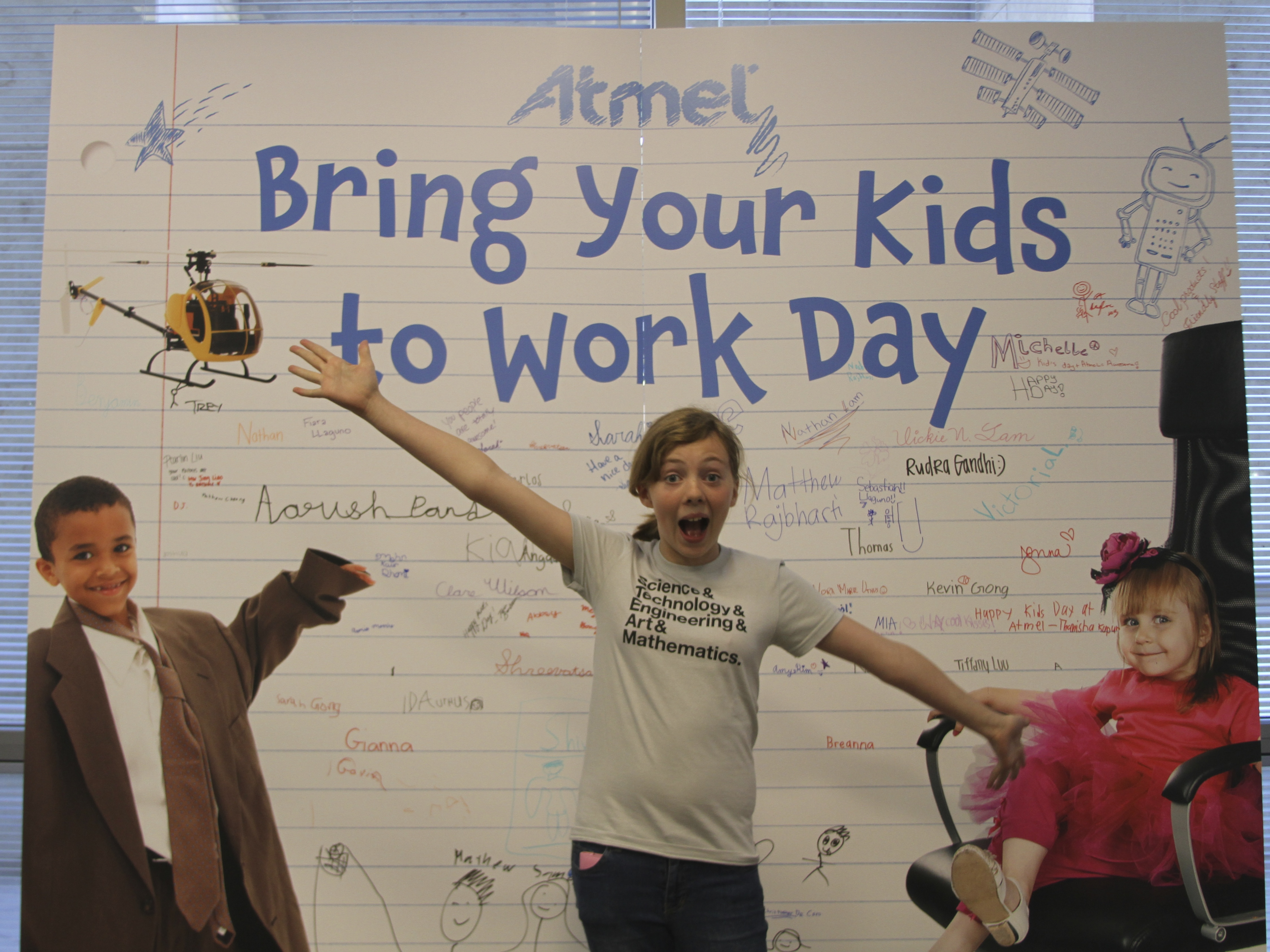
Super Awesome Sylvia and I were invited to attend Bring Your Kids to Work Day at Atmel recently. (Atmel, of course, is the company that makes the microcontrollers found inside Arduino products and in many of our own projects and kits.) We were there to help provide tangible, interesting, and playful examples of how Atmel chips can be used. And of course, we weren’t going to miss an opportunity to visit Atmel headquarters!
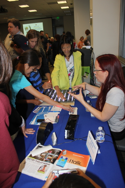
The biggest hit with the kids were the Octolively interactive LED modules (sporting the Atmel ATmega164P). When the kids waved their hands over them, the LEDs would light up and ripple. Some of the kids would start out by poking and grabbing at the LEDs until they lit up, but as soon as I told them it would work “even without touching it” their eyes would get big, and they’d wave their hands over the top, enthralled.
Some of the other things we brought were our handheld game, the Meggy Jr RGB (with the ATmega328P); a Bulbdial Clock (Atmega328P again), which points rings of LEDs at different heights down at a central point to create shadow hands of different lengths; our giant Alpha Clock Five (ATMega644A); and the Larson Scanner (ATtiny2313A), which lights up nine red LEDs to make a scanning robot eye.

Another project that captured the kids’ attention was a Keepon by BeatBots. Other demonstrations included a quadcopter and a hacked hexabot.

We got to have lunch in the bright sun in the courtyard with Avary Kent, who was demonstrating the PuzzleBox, a brain-controlled helicopter.

Sylvia got to give the PuzzleBox a try, triggering it to fly as soon as she concentrated hard enough.
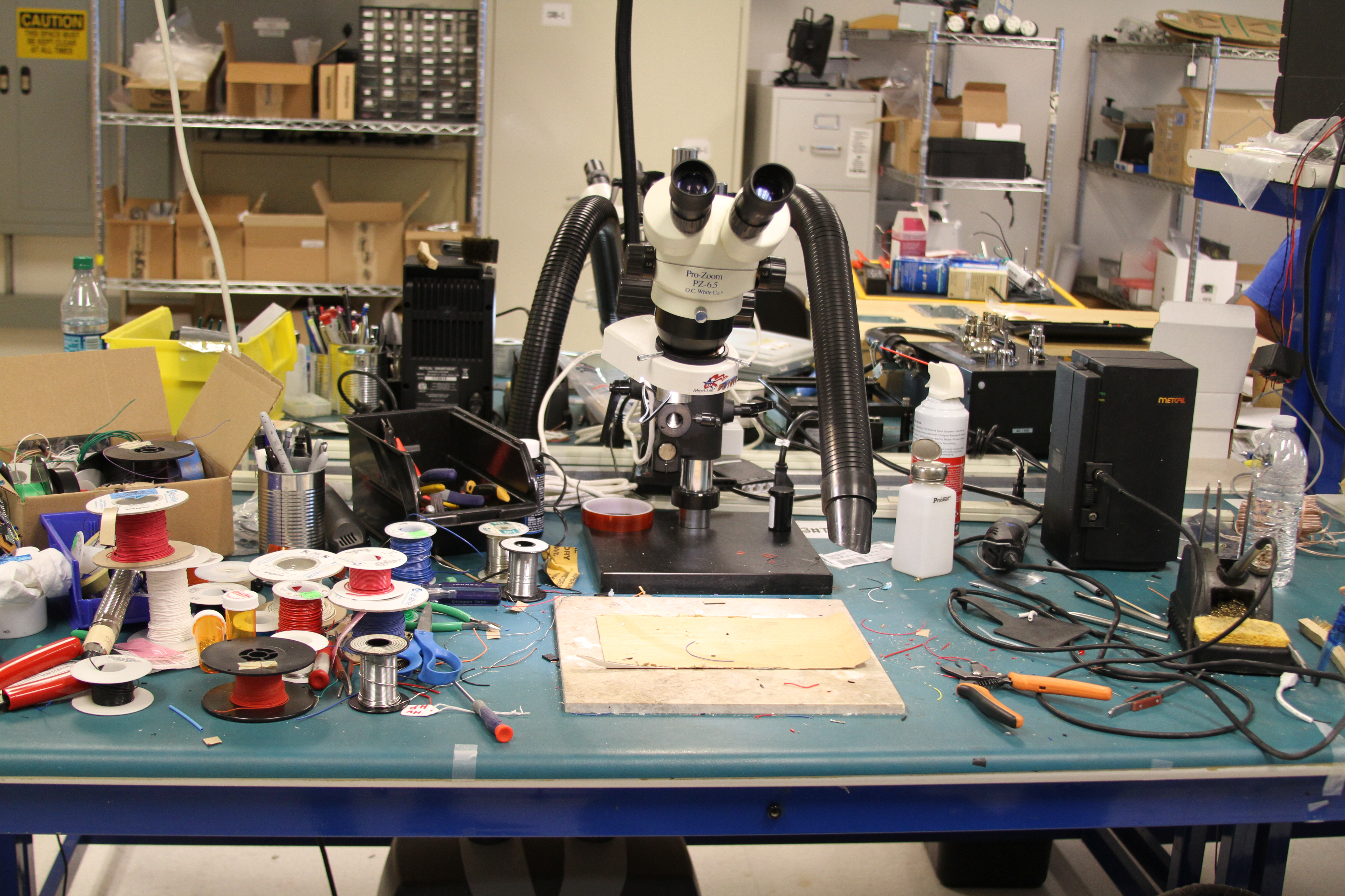
After lunch, we got to tour of a couple of labs. This workbench was well stocked with a Metcal soldering iron (our favorite) and lots of tools and supplies.
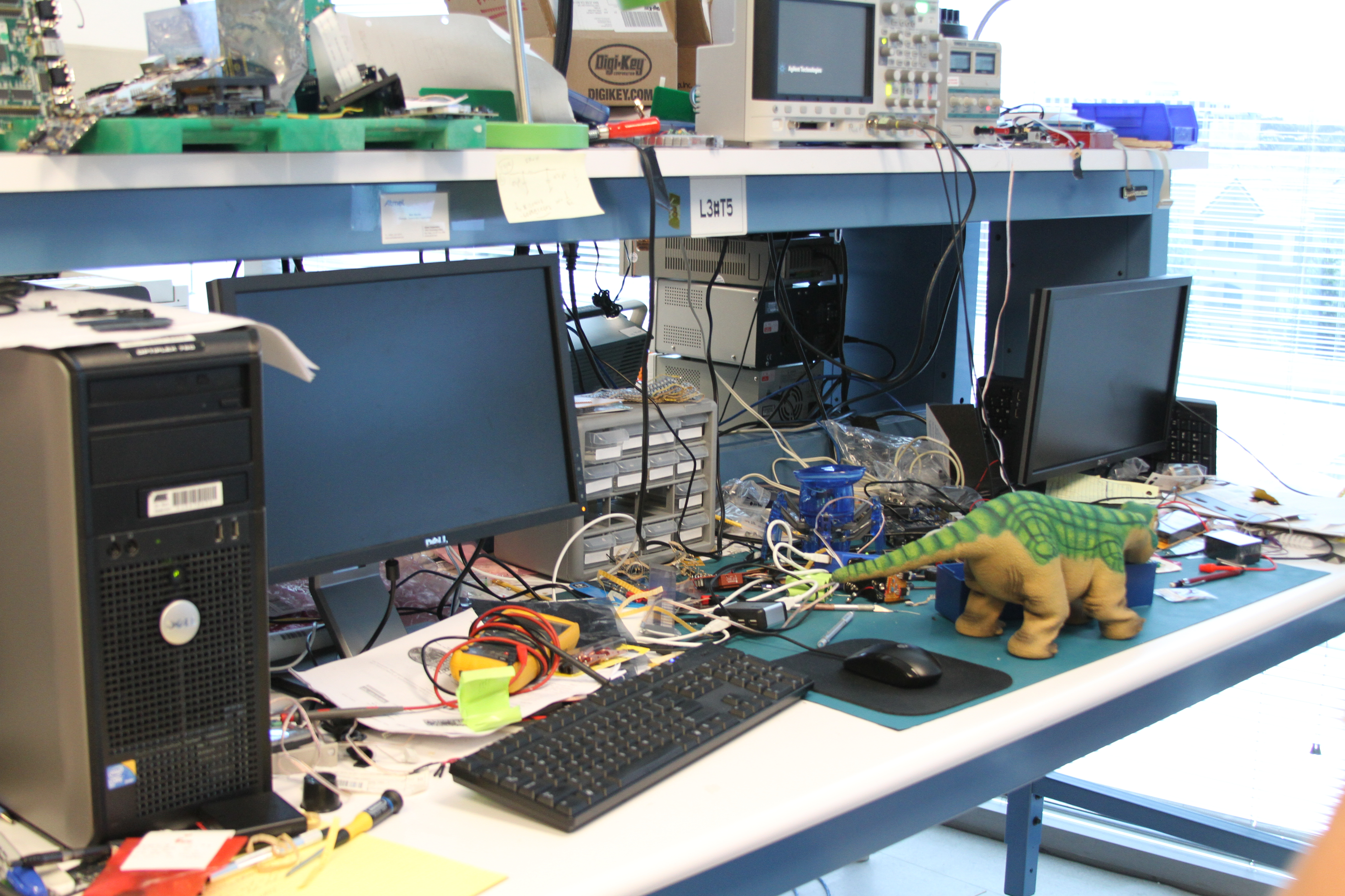
Apparently the poor Pleo on this bench needed some repair.
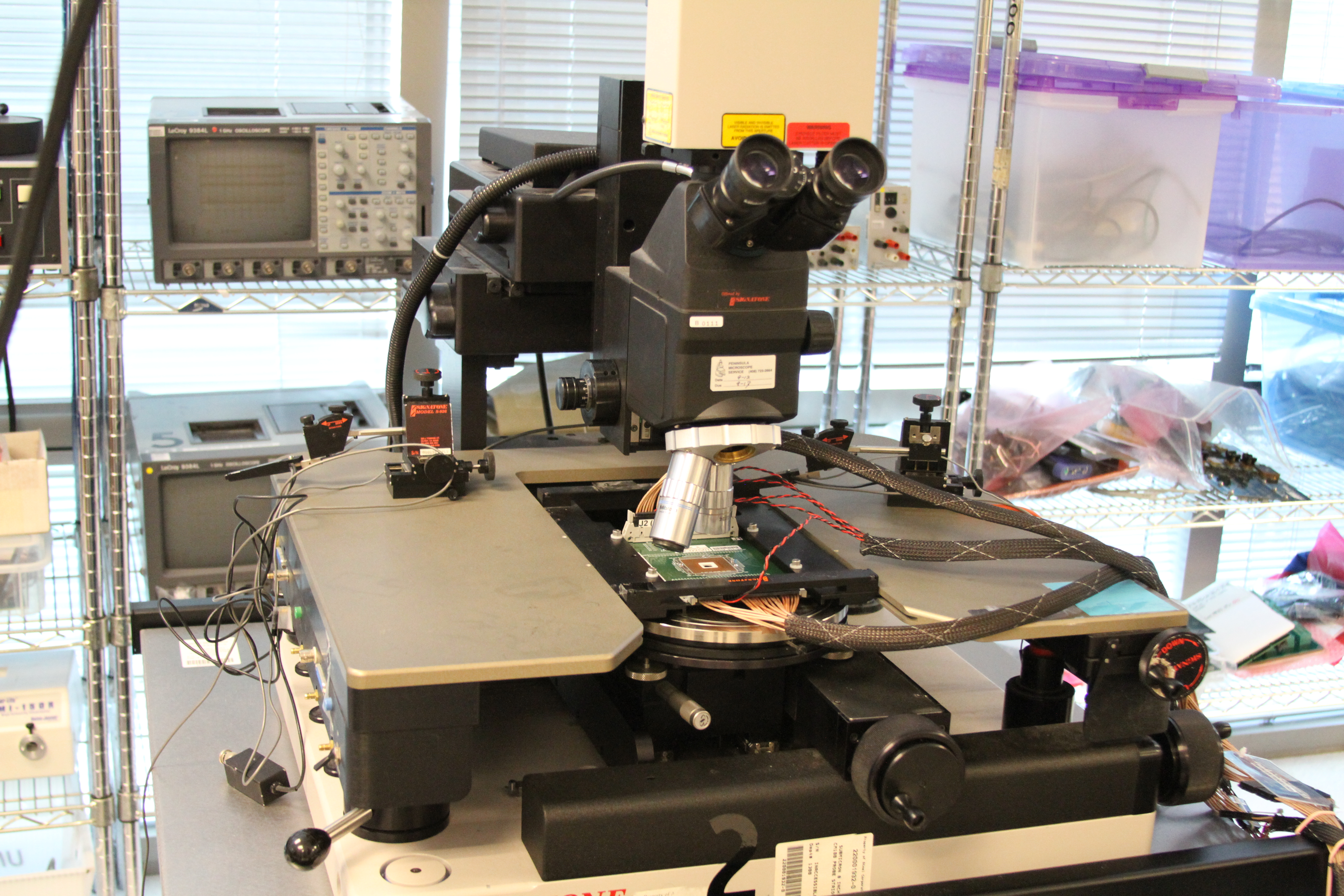
This machine is for inspecting and testing chips after they have been removed from their housing.
We got to go into the RF anechoic chamber, and watch as our cell phones stopped receiving any signals.
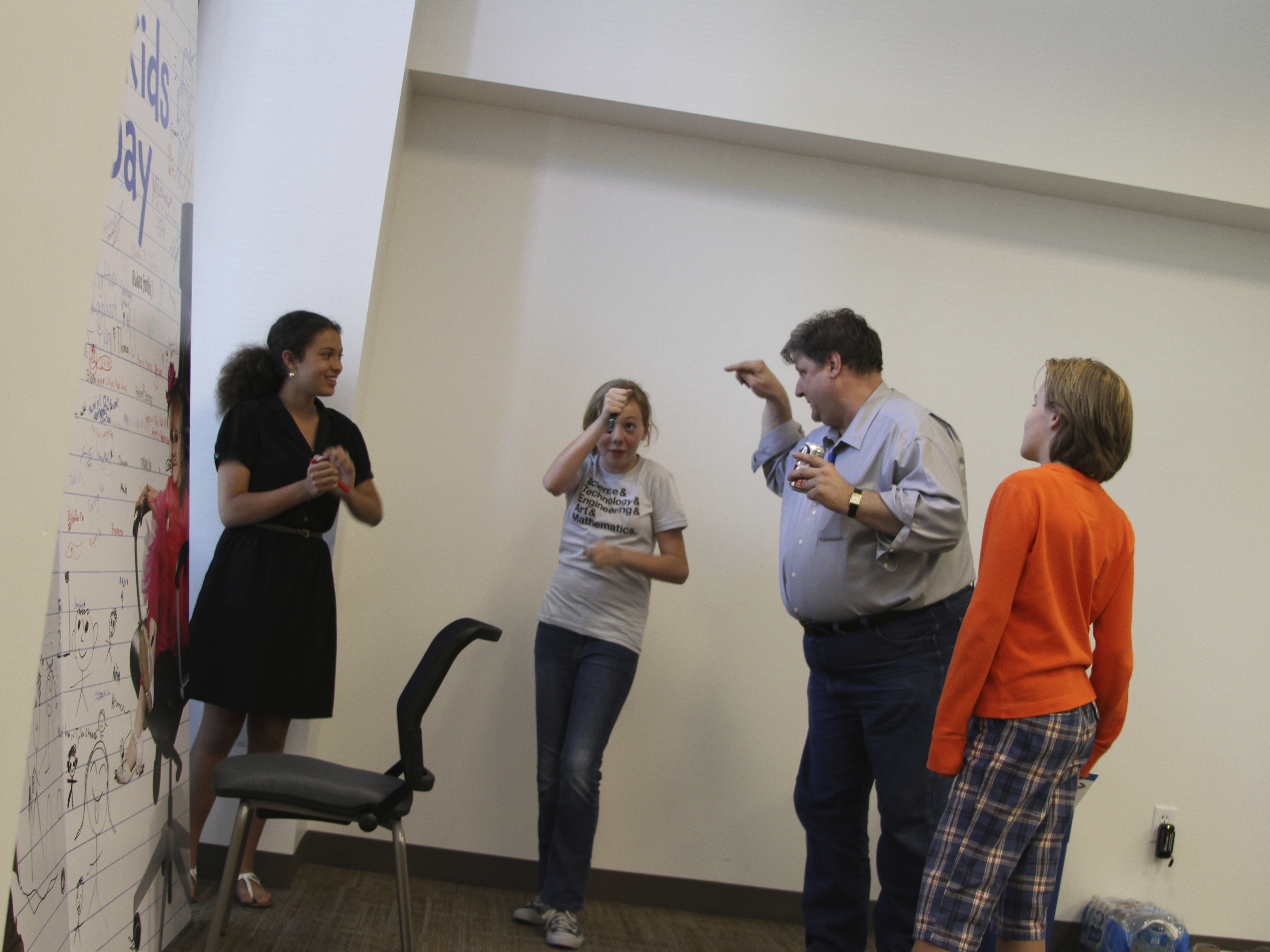
We also had some time to hang out and horse around with friends new and old. Our friend Paul Rako seemed to be having as much fun as the kids.

Thanks to Paul and Atmel for inviting us to visit!