What’s just like an
Eggbot but quite a bit larger? The all-new
Ostrich Eggbot!

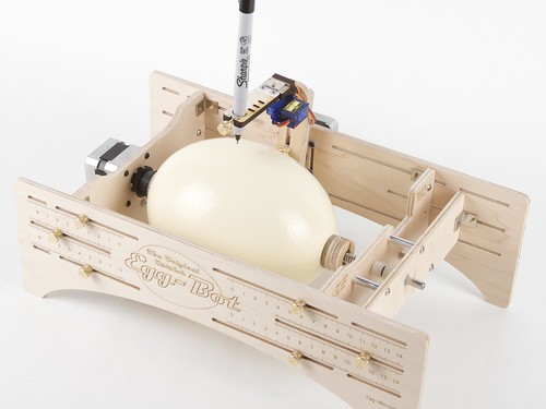
So yes, just like the Eggbot, it’s a machine capable of drawing on the surface of all kinds of spherical and egg-shaped objects. As the name implies, the Ostrich Eggbot is big enough to (very easily) fit ostrich eggs– one is shown above with a (rather large) chicken egg for scale. And, like the Eggbot, we’re releasing it as an open source kit.
Given all that, we feel confident to suggest that the Ostrich Eggbot may already be
quite possibly the worlds finest open-source CNC ostrich-egg decorating machine.
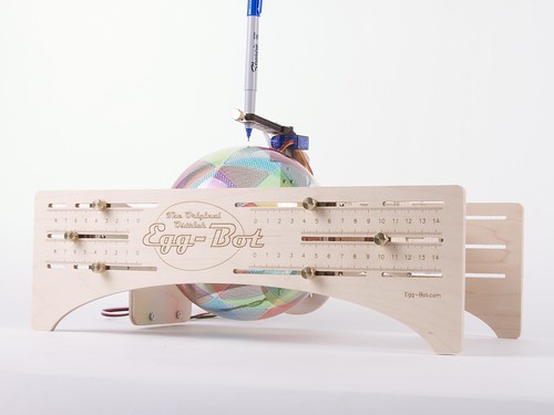
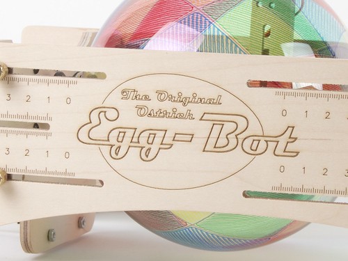
The Ostrich Eggbot chassis is CNC cut from hardwood plywood which is then laser engraved with calibration and assembly marks. Versus the original (standard-size) Eggbot, the feet have been moved to the sides for a wider base to give better stability with differently sized objects.
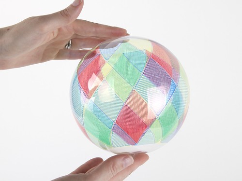
This is a glass ball, 6 inches in diameter, which has been decorated in a motley pattern, with some colored Sharpie markers– it almost looks like stained glass.

The range of printable objects extends from chicken eggs all the way up past ostrich eggs, and includes things like christmas ornaments, pool (billiards) balls, and all kinds of egg-shaped and spherical objects from 2.25 to 6.25 inches in diameter. (The blue-green alien-egg looking thing is an emu egg. It fits, too.)
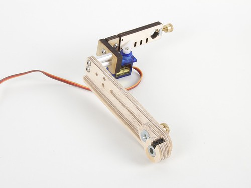
One of the big challenges in the design was that the new “pen arm” had to be much longer, and consequently to be much, much stiffer so that it doesn’t flex and flop around as the pen is moved.
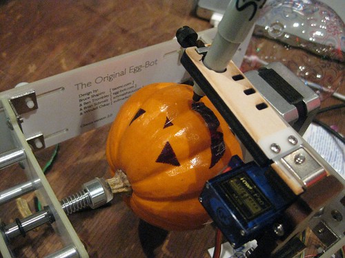
The new pen arm and its mount have been fully redesigned and are now CNC carved from 1/2″ hardwood plywood, which provides a stiffening member along the side. The top section of the pen arm– where the servo motor and hinged pen holder mount –can also now be mounted at two different heights. The lower register allows plotting on small-diameter objects (like chicken eggs) that would otherwise cause the bottom end of the pen arm to hit the tabletop where the robot is sitting.
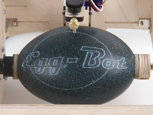
The Ostrich Eggbot uses the same pen holders (“distal pen arms” in the jargon) as the original Eggbot, so all the same range of pens, pencils, markers, chalk, and crayons can fit in the Ostrich version too. Especially cool is that the
engraver kit still fits, now making it possible to do things like engrave on emu egg shells.
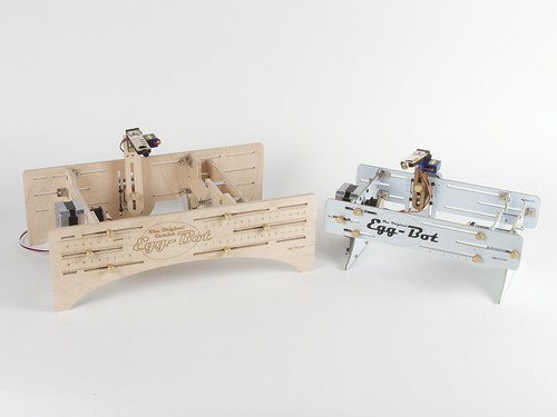
Here’s how the Ostrich Eggbot looks next to the original. The original Eggbot just about
fits inside the Ostrich Eggbot. The original size is still much better for working with smaller objects like ping pong balls and chicken eggs– but it only can draw on objects up to about 4.25 inches (10 cm) in diameter. The Ostrich chassis doesn’t go as small, but it does go up to 6.25 inches (16 cm) in diameter, and works with much longer objects as well.
The Ostrich Eggbot kit has the exact same “active” components– the same motors and
EiBotBoard driver board –as the Original Eggbot kit, so we’re making an
upgrade kit available (in addition to the
standalone version), for those who already have an Eggbot or want to be able to print on everything from very small to very large objects.
The
Ostrich Eggbot is available now at our webstore.
Documentation for the Ostrich Eggbot is hosted at the
Evil Mad Scientist Wiki, as a supplement to the more complete
Eggbot documentation, which is also hosted there.


