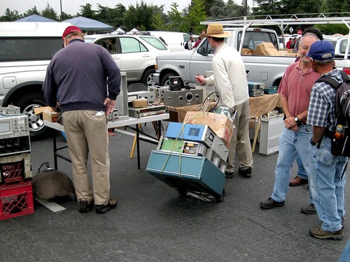
Last Electronics Flea Market of 2011, Saturday
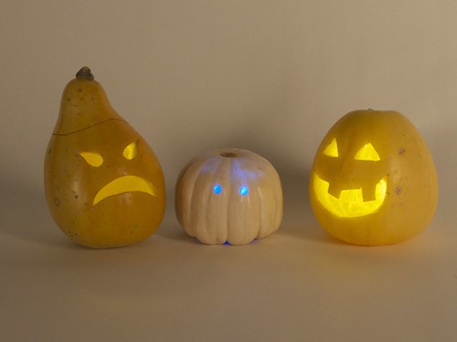
Basics: Simple LED Pumpkins
Awesome little LED Jack-o’-lanterns are quick and easy to build yourself, in the tradition of LED throwies.
Special bonuses: (1) Now with candle-flame flickering LEDs and (2) way brighter than those little LED tea lights!
Continue reading Basics: Simple LED Pumpkins
Improving open source hardware: Visual diffs
As the open source hardware movement matures, it’s worth taking a moment to consider the issue of version control.
Collaborative software projects make heavy use of version control– tools like Subversion and Git, and project hosting sites like SourceForge, GitHub, and Google Code –to organize and manage the contributions of many developers to a project. But as we begin to consider open source hardware, can we use these same tools and sites for effective collaboration on hardware projects?
The short answer is, “yes”– after all, people are already doing it. But the reality is that we could do much, much better. Some people think that we do need a separate “SourceForge for hardware.” That’s hard to say. But it is the case– perhaps against conventional wisdom –that existing tools can be used, today, for meaningful hardware version control.
It’s certainly possible to take any old binary file (say from a CAD program), and store it in a version control system. This is, in fact, how many of today’s open source hardware projects are managed. However, a “diff” (direct file comparison) to see what’s changed between two versions of a given file is all but meaningless.
For design files in plain-text (“ascii”) file formats, such as Inkscape‘s SVG or KiCad‘s .brd, a diff is possible and is in principle meaningful, but it is usually all but useless in practice, because CAD is a graphical sport, and we need to treat it like graphics.
An example: Suppose that you found the following snippet in the difference between two SVG files:
 <path
       sodipodi:type="arc"
       style="fill:#ff00ff;fill-opacity:1;stroke:#ffa6a6;stroke-width:0.18000001;stroke-linecap:round;stroke-linejoin:round;stroke-miterlimit:4;stroke-opacity:1;stroke-dasharray:none;stroke-dashoffset:0"
       id="path2816"
       sodipodi:cx="237.14285"
       sodipodi:cy="328.07648"
       sodipodi:rx="160"
       sodipodi:ry="84.285713"
       d="m 397.14285,328.07648 a 160,84.285713 0 1 1 -319.999997,0 160,84.285713 0 1 1 319.999997,0 z" />
You probably wouldn’t recognize that (at least not quickly) as a big magenta ellipse. While it’s perfectly legible as source code, a diff result like this would be all but useless in practice.
The obvious solution, is to add in some visual diffs in order to make sense of changes between design files. On the bright side, making these is remarkably straightforward, and– with a little bit of effort –practically supported by existing version control systems.
In what follows, we’ll walk through some examples of visual diffs– with bitmaps and PDF files –and discuss what you can do to help make version control work better for CAD files, and to make CAD files better for version control.
Continue reading Improving open source hardware: Visual diffs
In pictures: Maker Faire NY 2011
Maker Faire NY 2011 and the Digi-Comp II
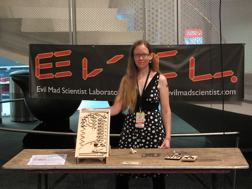 We’re here in New York for the 2011 Maker Faire New York (the “World Maker Faire”), held for the second year at the– absolutely fantastic —New York Hall of Science.
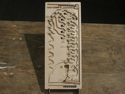
This weekend, we’ll be showing off an all-new prototype version of the Digi-Comp II. Back in May, at the Bay Area Maker Faire, we showed off a giant-scale version of the Digi-Comp II, documented here on our blog both in photos and with video.
Our new prototype is at the scale of the original (mid 1960’s) Digi-Comp II, which used half-inch diameter glass marbles. Rather than marbles, we’ve opted for half-inch diameter chrome steel balls–miniature pinballs or overgrown pachinko balls, depending on your perspective. The original machine was made of thin vacuum-formed plastic, supported by a sheet of masonite and fitted with injection-molded flip-flops and switches. While our final version will be fabricated from (very sturdy) vacuum-formed plastic, we’re currently in a phase of functional testing, using CNC-machined wooden versions.
Here is what the whole machine looks like. Despite using the same size ball, the overall size is a bit smaller than the original: 10×24″ versus 14×28.5″. From testing, it’s clear that there are some places that a little more vertical room would make for a more user-friendly design, so it is likely that our final version will be closer to 25-26″ in length.
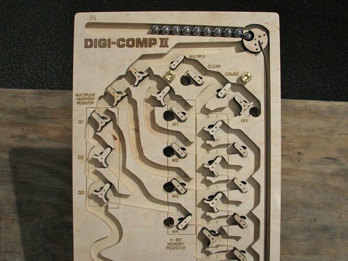 The top surface of the machine is cut from 1/2″ thick plywood, using a CNC router to make 3/8″ deep channels where the balls can roll. After routing, we added all of the labels by laser engraving. The flip-flops and switches are laser cut from thinner plywood, and rotate on simple plain bearings consisting of 1/16″ diameter stainless steel pins and slightly larger holes drilled through the wood. At the upper right, you can see the ball-release mechanism, which releases a ball when the actuated by the pushrod.
As with our giant model, the design is a functional but not exact replica of the original. All of the flip-flops, registers, and switches are approximately in the original locations, but the “wiring” (really, rolling ball paths) has been created from scratch. One of the non-obvious things when you first look at the Digi-Comp II is that there are actually two levels to the machine. The six “black holes” that you can see above drop the ball down to the lower level, as a shortcut to the bottom or (for certain functions) to flip switches on the top side.
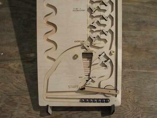 On the bottom half of the machine you can see the ball return as the stripy ramp in the center. The stripes on the ramp arise from cutting plywood at an angle (see here for another example). Below that is the Start Lever. When a ball presses down the start lever, it pushes the pushrod that releases the next ball from the top.
We’ll be demonstrating our prototype Digi-Comp II all weekend at Maker Faire. If you’re in the area, please drop come see the Maker Faire, say hi, and try it out!
- Additional resources:
- If you’d like more information about the Digi-Comp II in general, please take a look at our prior articles (again, with photos and with video).
- The official site for our project is digicompii.com
- If you are interested in the forthcoming kit version, please sign up for the Evil Mad Science Mailing List.
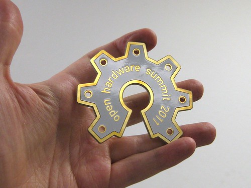
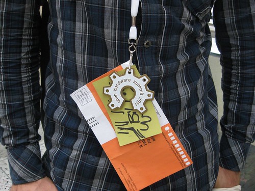
Open hardware summit badge
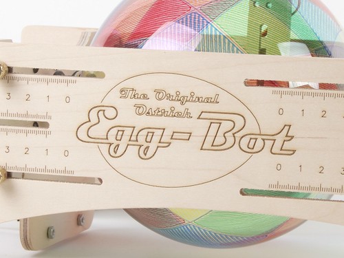
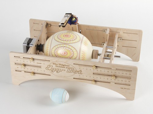
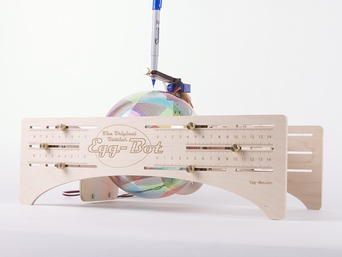
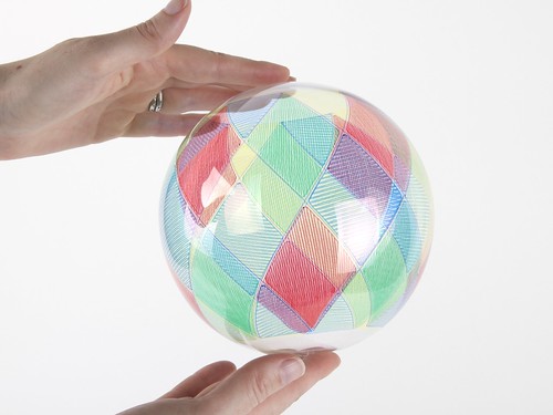
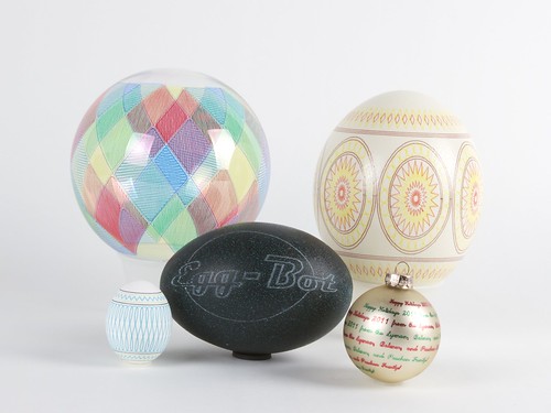
Ostrich Eggbot
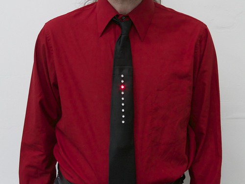
A new Kraftwerk-inspired LED tie kit?
Well, almost— With a breath of new firmware, our Larson Scanner kit takes us on a trip to the late 1970’s.
In the old videos of electronic music pioneers Kraftwerk performing their classic The Robots, a prominent prop is the animated LED necktie worn by each member of the band. If you haven’t seen this, or it’s been a while, you can see it right here at YouTube. (Additional viewing, if you’re so inclined: Die Roboter, the German version.)
The Kraftwerk tie has nine red LEDs in a vertical row, and one lights up after the one above it in a simple descending pattern. And what does it say to the world? One thing only, loud and clear: “We are the robots.” Now, if you’re anything like us, the most important question going through your head at this point is something along the lines of “why am I not wearing a tie like that right now?”
The good news is that it’s actually easy to make one. And the starting point? A circuit with nine red LEDs and just the right spacing: our open-source Larson Scanner kit. With minor modifications– a software change and dumping the heavy 2xAA battery pack–it makes a pretty awesome tie. In what follows, we’ll show you how to build your own, complete with video.
Microwave Oven Diagnostics with Indian Snack Food
Microwave ovens are curious beasts. A super convenient method of warming up certain foods, for boiling a cup of water, melting a little butter, or reheating frozen leftovers. But all too often, those frozen leftovers end up scorching in places and rock-hard frozen in others. Is this just random? Is it really the case that microwaves cook the food from the inside out or left to right or back to front? Well, no, but the way that microwaves work can be mighty counter-intuitive.
Our own microwave oven is definitely one of those that likes to produce scalding yet frozen output. That isn’t necessarily such a big deal if you have patience to reposition a dish several dozen times in the course of a five minute warm up. But we recently (and quite unintentionally) came across a situation– while cooking, of all things –where the radiation pattern became clear as day.
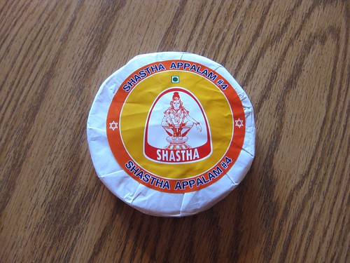
As we have written about, we enjoy roasting papadums (a type of Indian cracker) on the stovetop. Appalams are a closely related cracker made with rice flour in addition to the usual lentil flour that can be cooked in the same ways, but just happen to be significantly more flammable.
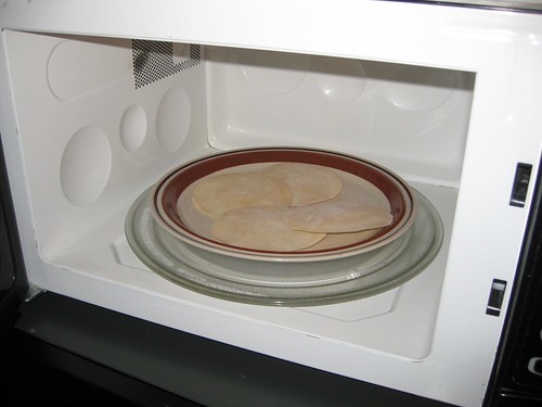
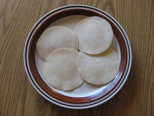
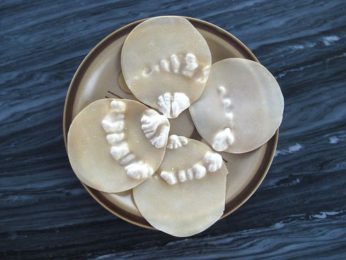
So, while you can (with great care and a nearby fire extinguisher) roast appalams on the stovetop, we decided to try out the microwave method. We put several of the appalams on a plate. They start out as plasticky brittle wafers like you see above.
And then, after 30 seconds in the microwave, here is what we saw:
Holy crap!
As an area of the cracker cooks, it bubbles up in just a few seconds, leaving clear marks as to where there is microwave power and where there isn’t. For this particular microwave, Saturn-shaped objects will cook evenly.
Obviously what is happening is that there are two hotspots in this microwave: one in the center, and one offset from center which traces out a circle thanks to the rotating plate in the bottom.
We have access to four other microwave ovens. Are they all this bad? Continue reading Microwave Oven Diagnostics with Indian Snack Food


