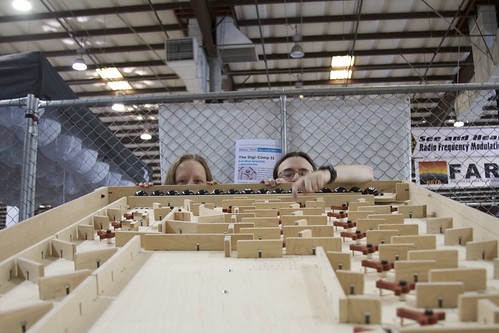
 We’re here in New York for the 2011 Maker Faire New York (the “World Maker Faire”), held for the second year at the– absolutely fantastic —New York Hall of Science.
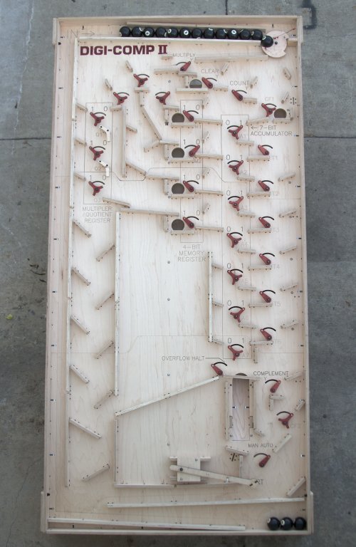
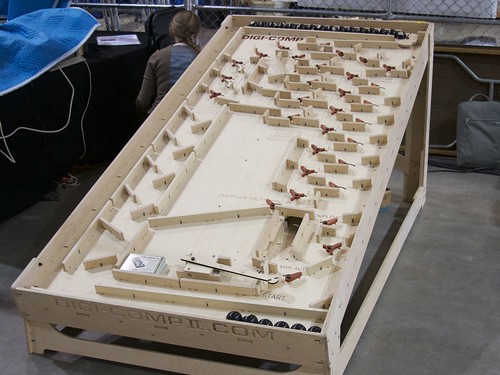
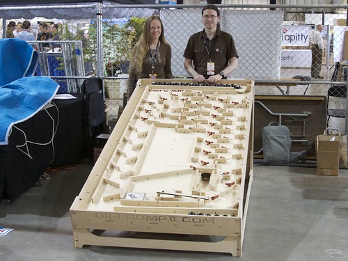
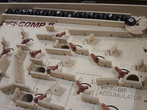
This weekend, we’ll be showing off an all-new prototype version of the Digi-Comp II. Back in May, at the Bay Area Maker Faire, we showed off a giant-scale version of the Digi-Comp II, documented here on our blog both in photos and with video.
Our new prototype is at the scale of the original (mid 1960’s) Digi-Comp II, which used half-inch diameter glass marbles. Rather than marbles, we’ve opted for half-inch diameter chrome steel balls–miniature pinballs or overgrown pachinko balls, depending on your perspective. The original machine was made of thin vacuum-formed plastic, supported by a sheet of masonite and fitted with injection-molded flip-flops and switches. While our final version will be fabricated from (very sturdy) vacuum-formed plastic, we’re currently in a phase of functional testing, using CNC-machined wooden versions.
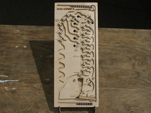
Here is what the whole machine looks like. Despite using the same size ball, the overall size is a bit smaller than the original: 10×24″ versus 14×28.5″. From testing, it’s clear that there are some places that a little more vertical room would make for a more user-friendly design, so it is likely that our final version will be closer to 25-26″ in length.
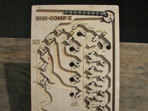 The top surface of the machine is cut from 1/2″ thick plywood, using a CNC router to make 3/8″ deep channels where the balls can roll. After routing, we added all of the labels by laser engraving. The flip-flops and switches are laser cut from thinner plywood, and rotate on simple plain bearings consisting of 1/16″ diameter stainless steel pins and slightly larger holes drilled through the wood. At the upper right, you can see the ball-release mechanism, which releases a ball when the actuated by the pushrod.
As with our giant model, the design is a functional but not exact replica of the original. All of the flip-flops, registers, and switches are approximately in the original locations, but the “wiring” (really, rolling ball paths) has been created from scratch. One of the non-obvious things when you first look at the Digi-Comp II is that there are actually two levels to the machine. The six “black holes” that you can see above drop the ball down to the lower level, as a shortcut to the bottom or (for certain functions) to flip switches on the top side.
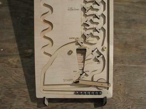 On the bottom half of the machine you can see the ball return as the stripy ramp in the center. The stripes on the ramp arise from cutting plywood at an angle (see here for another example). Below that is the Start Lever. When a ball presses down the start lever, it pushes the pushrod that releases the next ball from the top.
We’ll be demonstrating our prototype Digi-Comp II all weekend at Maker Faire. If you’re in the area, please drop come see the Maker Faire, say hi, and try it out!
- Additional resources:
- If you’d like more information about the Digi-Comp II in general, please take a look at our prior articles (again, with photos and with video).
- The official site for our project is digicompii.com
- If you are interested in the forthcoming kit version, please sign up for the Evil Mad Science Mailing List.


