We found this gem in A Manual of Engineering Drawing for Students and Draftsmen, 9th Ed., by French & Vierck,1960, p. 487.
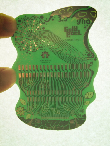
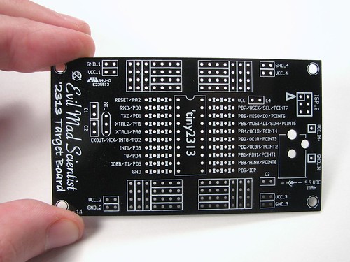
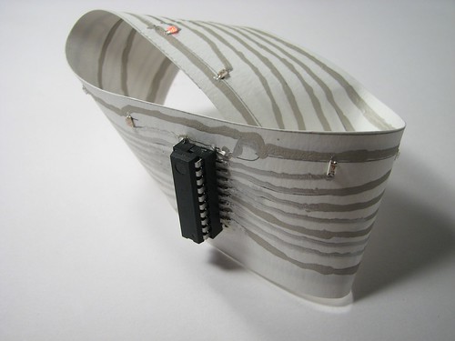
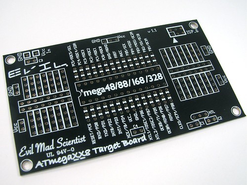
Printed Circuits allow miniaturization and the elimination of circuit errors—advantages that cannot be obtained by other methods. Once a pattern or suitable design is established, preparation of a black and white drawing can start. Scales for reduction, for example, 4 to 1, 3 to 1, or 2 to 1, are used. To insure sufficient bonding area of the metal laminate during soldering operations, lines should not be less than 1/32 inch in width when reduced. Line separation should never be closer than 1/32 inch on the final circuit. Figure 19.24 illustrates the drawing of printed circuits.


