Tag Archives: peggy 2

3D LED POV Mirror

“We Are with You, Mirror” is a piece by Brady Marks from VIVO Media Arts Centre that was shown at the Vancouver Mini Maker Faire. It is a 3D persistence of vision volumetric display that acts as a mirror, using four spinning Peggy 2 boards to reflect visitors movements in low resolution 3D LED glory.

Thank you to Brady for sending in the video!

Surface Mount LEDs on a Through-hole PCB

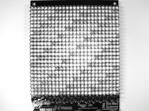
Peggy 2le Surface Mount

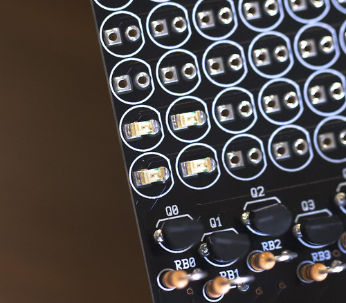
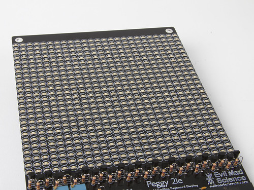
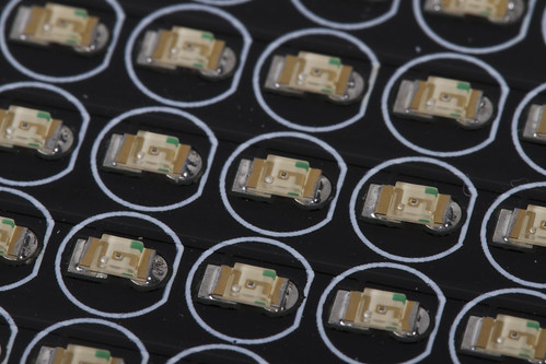
Peter T. recently stopped by our shop with his Peggy 2LE and showed us his incredibly cool hack. He had noticed that the 0.1″ pin spacing for a standard through-hole LED is just about perfect to accommodate LEDs in a 1206 surface mount package.

Peggy 2le Surface Mount

Once he had finished populating all the LED locations, he brought it by again. He used an alignment jig he had made to keep everything in straight rows while soldering.

Peggy 2le Surface Mount

The surface mount LEDs look great on the grid designed for T-1 3/4!

Peggy 2le Surface Mount

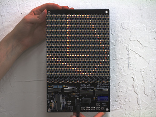
We plugged it in so we could see his pretty orange LEDs in action. Thanks to Peter for bringing it by and letting us take pictures!

Senko [Flash]

Tatsu Iida, a member of oxoxo [zero by zero] wrote in to tell us about the interactive LED installation entitled Senko [Flash] which they showed at the Tokushima LED Art Festival in April.

senko-body

They used a Peggy 2 to drive a field full of LED illuminated spheres, along with IR sensors to detect visitors entering the array. Each new person would trigger a new sphere to light up and move through the field.

?? [Senko] - Tokushima LED Art Festival

This is the largest installation we’ve ever seen based on the Peggy 2.

?? [Senko] - Tokushima LED Art Festival

Thanks for sharing your incredible project with us!

Links to many more Peggy 2 projects are on the wiki.

Infra, a TV built from remote controls

Chris Shen‘s first solo show just opened at 18 Hewett Street in London, and he shared with us about his piece, Infra, built using a Peggy 2:

The idea was to build a infrared display out of old remote controls, using the existing infrared LEDs as pixels of a low-res display. 625 old remote controls are mounted in a metal frame connected by individual wires to a modified Peggy 2 that runs the whole installation.

The main change to the Peggy was to solder molex headers instead of LEDs: this is to allow the wires to be easily plugged in and out of the board which is necessary when dismantling and reassembling the piece. Yes, all 625 remotes are numbered so they can be removed from the frame for transportation! The current and voltage was also adjusted fo IR LEDs as opposed to visible LEDs.

While researching, the main thing I was looking for was the ability to play video (live) on a low-res matrix. I looked into various ways of doing this but once I found the Peggy 2 kit it gave me confidence to go ahead with building Infra because of the open-source nature,  existing work done by Windell, and Jay Clegg’s video Peggy mod.

I connect all the remote controls via 500 meters of speaker wire to the Peggy, held into the frame by a simple looped elastic band. The circuit is mounted to a sheet of acrylic as the circuit bowed with all the wire attached. Each remote had to be opened to solder the wire directly to the LEDs legs. The wire is then routed out through the back of the remote and closed back up.

Preparing all 625 remote controls was the most time consuming part, each was different and often not very clean especially once you get inside. Although looking at all of the remotes individually revealed another side to the project which I’ve documented through a small run of books.

Thank you to Chris for sharing about how you made your piece with us. His exhibit will be up through February 3rd, 2013, so if you’re in London, go see it soon!

Peggy 2 Station Clock

Simon Jelley, the winner of our Peggy 2 Clock Concept Contest back in 2010, posted about how he took his prize and built his proposed clock: a video display of an analog clock face based on the clock in Victoria Station.

peggyvictoria

It looks even better in its physical manifestation than it did as a concept.

Thanks for sharing your project, we’re thrilled to see that you made it happen!

Another wild Peggy 2 project: Heddatron Robot

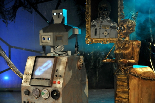
The folks at Chibots helped the Sideshow Theatre with building the robots for their 2011 production of Heddatron that was part of the Steppenwolf Garage Rep series. For the character Billy Bot, they used a Peggy 2 as a chest display panel which could be controlled remotely along with the rest of the robot actions and behaviors during the performance.

Don from Chibots wrote:

I got to assemble it (625 LEDs!), and made some modifications to the control circuitry to accommodate needs of the remote controls.  The robots were controlled via X-Bee Pro radio transceivers coupled to BahBot MCU boards. Of course, the solidly-designed Peggy 2 worked perfectly out of the box.

The production won a Jeff Award in the Artistic Specialization category for Outstanding Achievement in Robot Design and Engineering.

Billy Bot was even called on to help with a surprise wedding proposal after one of the shows, and you can see him in action briefly in the video above.

Awesome robot work, Chibots!

Photos courtesy the Sideshow Theatre Company.

Peggy 2 with sockets

Untitled

Paul Gerhardt of Lockitron built this awesome Peggy 2 (our LED “pegboard” kit), where instead of directly soldering in all of the LEDs, they’re mounted in sockets so that they can be moved around easily.  Now, this isn’t the first time that we’ve seen a Peggy filled with sockets, but— thanks to Paul’s clever trick —it is the first time that we’ve seen it done well.

Usually, when someone fills a Peggy up with sockets, it ends up looking something like this:
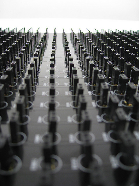
IMG_0381.jpg

As you may be able to see, the usual problem with installing an array of sockets this large is that it is very difficult to keep the sockets aligned neatly. Corey Menscher made a socketed Peggy for an ITP project, and his photo above demonstrates the problem.

IMG_0401.jpg

Once you add the LEDs, small offsets in socket alignment translate into larger angle variation in the LEDs that are put into them.  We’ve usually gotten around this problem by soldering the LEDs directly into the holes, so that the LEDs are flush against the circuit board and stay level and aligned.
Untitled

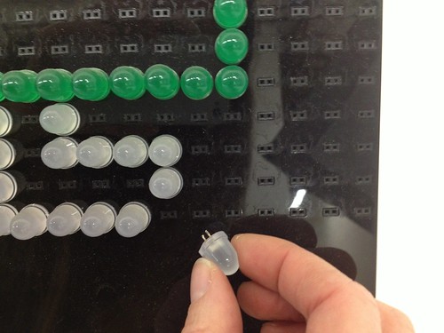
Paul solved the problem by making a laser-cut acrylic overlay that fits around the sockets, holding each one squarely in position, and also providing a level surface to push the LEDs against, so that they all stay level and aligned.
Untitled

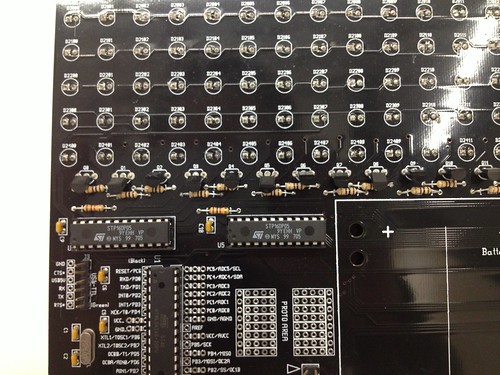
A second trick that he used is to solder all of the LED sockets into the back side of the PCB, so as to avoid any height interference with other components.  So instead of LEDs, the on the “front” side of the Peggy, you just see the tail ends of the sockets.  Then, the acrylic overlay can be just at the height of the sockets for the entire board, giving the whole thing a clean, sleek look.
Untitled

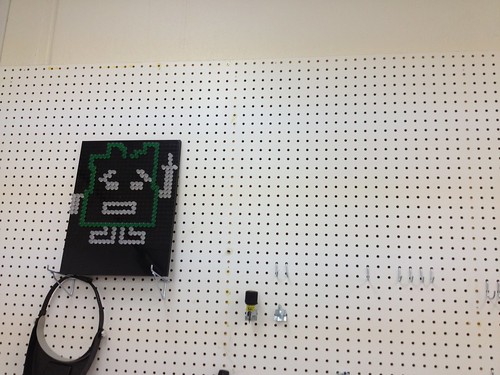
To add just one more layer of awesome, he’s hanging his Peggy on a pegboard.  (Now, we just need to route power up through the holes.)   Thanks, Paul, for sharing your clever hack.

A Peggy 2 Word Clock

Evil Mad Word Clock

Justin Shaw of WyoLum recently presented with this little slice of awesome: One of our own Peggy 2 kits, adapted into a great big “word clock” with the help of custom software and laser-cut acrylic.

WyoLum is a small but international collective of Open Source Hardware enthusiasts who collaborate on hardware designs and other projects (like their Open Hardware Grants) that promote Open Source Hardware.   One of their great ongoing projects has been a series of open source word clocks, ClockTHREE and ClockTHREEjr, which drew inspiration from a number of sources including QlockTWO, Doug Jackson’s word clocks, and the open source design of our Peggy 2 kit.

This is, of course, one of the great things about designing Open Source Hardware: seeing unexpected uses. When we first released the Peggy 2, we didn’t even remotely consider that others would later use our circuit diagram for tips on building their own RGB word clocks.  And now it’s especially neat to see it come full circle, with the ClockTHREE software adapted to work back on the Peggy.

WyoLum’s design files for the Peggy 2 word clock are available for download here (by kind permission), and if you’re building one, you may also find helpful the ClockTHREE repository and our own documentation page for the Peggy 2.

Photo by Brian Krontz of WyoLum.

Mailbag: Hacking a Mega-Peggy

grayscale

Tony writes in with a question about hacking our DIY LED matrix kits:

“I’m building a Peggy 2LE. I have completed the wiring with the exception of the LEDs. I have constructed an external frame which has 600 mounting points for my LEDs using a Matrix design of wires crossing every 3 inches. Since the Peggy 2LE has 625 LEDs I need to know how I can drive the 30 anode connections and 20 cathode connections to the wiring them to the Peggy 2. Or am I going to have to wire each LED to the PCB of the Peggy + and – LED locations?”

And, that’s actually an interesting topic.  We’ve written before (here and here) about some giant-scale variations and modifications to our Peggy 2 and Peggy 2LE LED matrix kits, but we haven’t really addressed how one might go about building it.

First off, since you asked— and though we recommend against it —it is indeed possible to build an off-board LED matrix by simply running individual running wires from every LED location on the Peggy circuit board to every LED.  There are 625 LEDs in a 25 × 25 grid, and if each has two wires… that turns out to be quite a few wires.

MakerFaire2011 - 144

While *ahem* labor intensive, this method does work. We know this partly because several people have actually done it.  The “rats nest” of thin, red-lacquered magnet wire shown above is one example, and the Peggy shown here is another victim example of this method.

Fortunately, very fortunately, there are easier ways: think 50 wires, rather than 1250. And, there are a few other clever tricks that you might want to consider when changing the size of the matrix.  For example, it’s possible to use the Peggy 2LE to drive an off-board LED matrix of size up to 25 × 32 without adding any other extra hardware.

Continue reading Mailbag: Hacking a Mega-Peggy

Return of the Peggy Projects

One of the great things about building electronics projects is seeing what they inspire other people to do, and the 625 LEDs of the Peggy 2 can be pretty inspiring:

Mark at awe.com did some awesome scrolling text on Peggy 2 and has even shared his sketch for others to use. His video is embedded above or you can click on over to YouTube.

Phillip at peilipu’s posterous hooked up a Peggy 2LE and a Danger Shield to play Pong, a game we’re rather fond of.

Nick over at NJS Shredding wired up an off-board Peggy 2, neatly built into a wooden box and mounted to the ceiling. He also posted a video which shows the scale of it quite well.

Another ceiling mounted Peggy 2 installation was recently posted on the Make blog. This one, with an amazing array of ribbon cables connecting strips of LEDs, is entertaining visitors at the Children’s Museum of Pittsburgh and was created by the late artist Rick Gribenas. Thanks to Matt Mets for sending us the picture!

Also at a museum in Pittsburgh, Deren Guler used a Peggy 2 in a kid-powered generator exhibit at the Carnegie Science Center. Thanks for sending the picture, Deren!

You can read more about Peggy 2 on our store here, and full documentation is available on our wiki here and links to more projects are posted there as well.