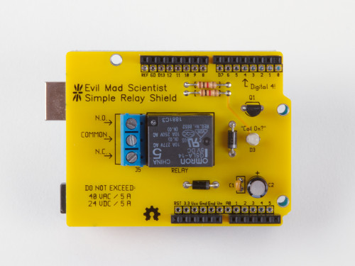
Introducing our newest kit: the Evil Mad Scientist Simple Relay Shield for Arduino.
It’s a dead-simple single-purpose low-cost mechanical relay board, with a single low-power SPDT relay that can switch moderate loads of up to 5 A, AC or DC.

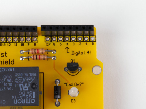
The relay is controlled by digital line 4— and that’s well labeled, too.
No library is needed. For a demo, just open the Arduino “Blink” example sketch and change the LED pin to 4. When output Digital 4 on your Arduino is low, the relay is in the “normal” state: the “Common” pin of the screw terminal is connected to the N.C. (“Normally Closed”) pin of the screw terminal.
When output Digital 4 goes high, the “Coil On?” LED will light up and the relay enters (for lack of a better term— suggestions welcome!) the “abnormal” state, and the Common pin is instead connected to the N.O. (“Normally Open”) pin of the screw terminal.

One of the main concerns about using higher voltages and/or currents on an Arduino shield is that you potentially have these things wired awfully close to things sticking up from your Arduino board, like the microcontroller itself or the USB connector. If you sometimes would like a little more breathing room, a good solution is to add the insulator shield Googly Eye Shield between the two.

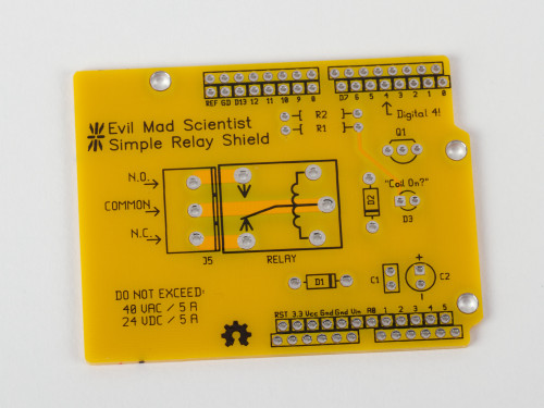
The Simple Relay Shield circuit board is a standard 2-layer, 1/16″ thick FR-4 PCB, but with highly-visible yellow soldermask. While it is (yes) very simple, the Simple Relay Shield is an open source hardware project. The circuit board is designed in gEDA, and the design files are available for download at the Evil Mad Science Wiki.
The Simple Relay Shield is available now at Evil Mad Science.


